
Mechanical Kits T-Rex
The T-Rex was produced by Timberkits and packaged for sale by both Timberkits and Mechanical Kits. Mechanical Kits is the US distributer for Timberkits.
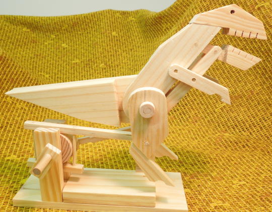
Finished model.
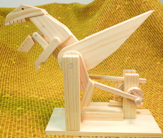
Finished model.
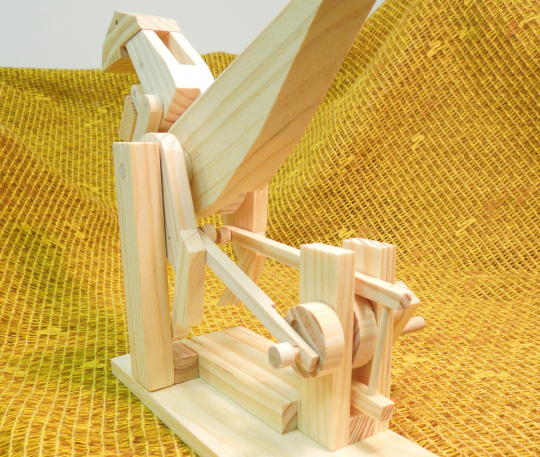
Finished model.
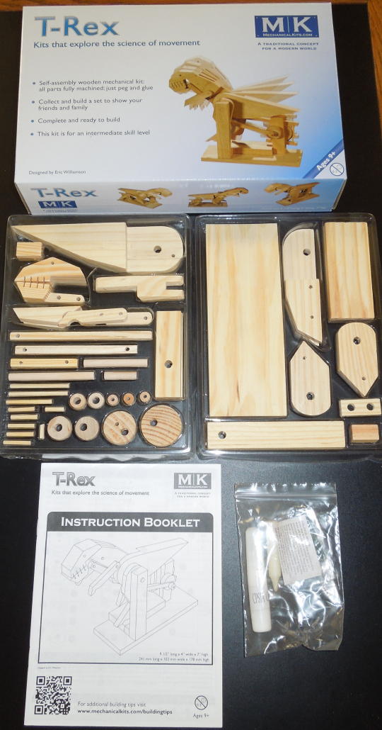
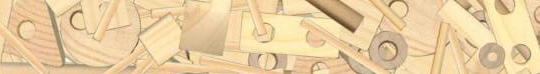
Box, parts and instructions.
Keeping the holes aligned while gluing the lower leg assemblies to the main body parts was tedious. What's needed is an alignment peg. Here's what I would do if building this kit again. Step 1 is building the crank assembly. The 25mm x 6mm bamboo rod handle (part 32) isn't necessary to assemble the rest of the kit. Set the handle aside as an alignment peg. When the rest of the model is finished, the handle can be glued into the crank where it belongs.
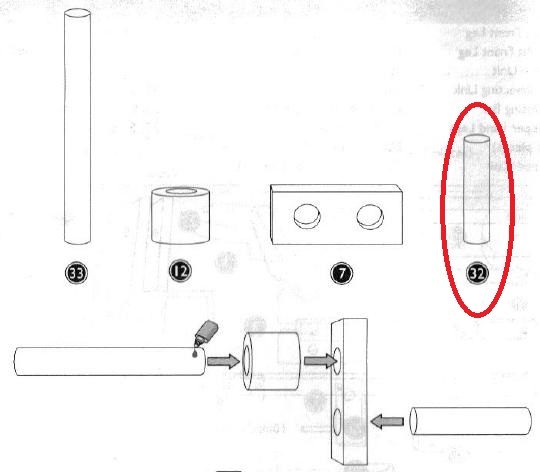
Set the handle (part 32) aside as an alignment peg.
Use the handle/alignment peg to keep the holes aligned when gluing the lower left leg and tail unit parts. Don't get glue on the handle!
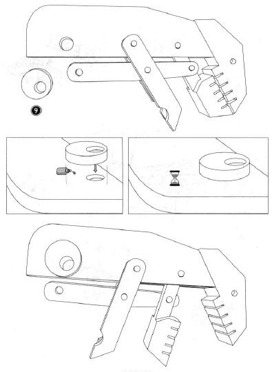
Use the handle/alignment peg to keep the holes aligned when gluing the lower right leg and neck parts.
After the rest of the model is finished the handle can be glued into the crank where it belongs.
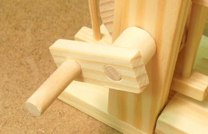
I screwed up the lower right leg by gluing the bamboo rod on the wrong side. Using a razor saw I cut off the protruding rod. Then I re-drilled the hole on the correct side of the leg, but only to a depth of about 3/16". I re-glued what was left of the rod into the new hole. The picture below shows my recovery. The right leg rod is shorter, but still long enough to accommodate the connecting link and spacer.
The right leg rod is shorter, but still long enough to accommodate the connecting link and spacer.
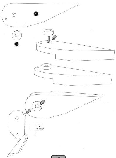
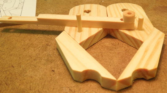
The instructions call for the lower left leg assembly to be glued to the tail unit at a 90 degree angle. Instead of trying to eyeball 90 degrees I partially mocked up the leg and tail without glue. With the crank turned such that the leg was fully forward, I made sure there was plenty of clearance between the tail unit and the main shaft support blocks. I made a pencil alignment mark between the leg and tail assemblies then glued the parts on the mark.
Aligning the lower left leg and tail unit.
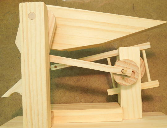
I wasn't clear about how to properly align the lower right leg and neck assemblies. This took some experimentation. Again I mocked up the model, but without gluing the right leg assembly to the neck assembly. I made a pencil alignment mark between the right leg assembly and neck assembly. Then I turned the crank and manually moved the neck while ensuring I could keep the marks aligned without any part of the model binding up. It took a few iterations to get just right. After gluing the leg to the neck and retesting the model, I glued all the remaining spacers to secure the connecting links between the crank/cam assembly and the left and right lower legs.
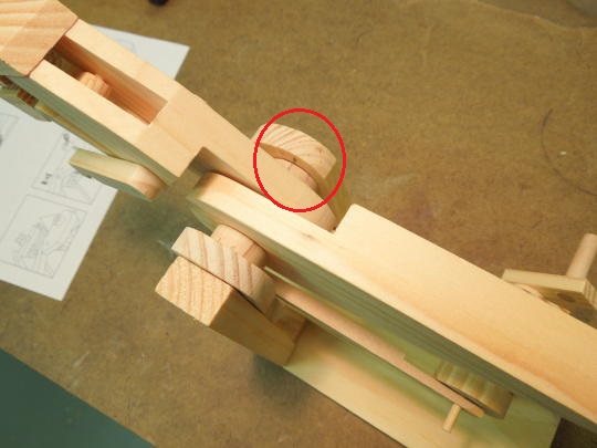
Alignment mark between the lower right leg assembly and the neck assembly.
Gluing the slab (part 2) to the base (part 3) involved a large surface area of moist glue. After the model was finished I noticed that a slight warp had been added to the base. If I had to do it again I would have firmly clamped the base down to a hard flat surface while the glue thoroughly dried.
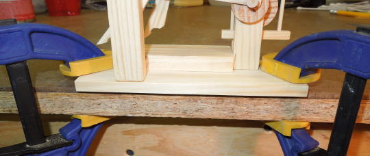
Clamp down the base overnight after adding the slab.