

Repair & Maintenance Log
10/28/13: Acquired a new CPR reproduction plastics set. I thought I might own this game someday.
07/31/14: Acquired a new CPR translite-to-backglass conversion mirrored backglass. Who'd've thought I'd find a game two days later?
08/02/14: Acquired game.
08/21/14: Installed standard-keyed (751) lock on coin door.
08/21/14: Added remote battery backup. Instead of permanently soldering some sort of remote battery setup to the CPU board I made battery place-holders from ½" dowel. This method required no board modifications. And no connectors were needed between the board and the battery pack. The battery pack was from Great Plains Electronics. I like that the pack is fully enclosed. I don't like that it has an integral ON/OFF switch. I set the switch to ON and put a blob of silicone caulk over it. The battery wires are mounted to an end of each dowel with a screw and crimp terminal. The screw head becomes the "battery terminal". Don't forget to account for the height of the screw head when figuring the length of the dowel. I wired the battery pack with 8' leads. Instead of placing the battery pack in the head, I dropped it down into the body and placed it next to the cash box. Opening the coin door is easier than opening the head. The idea is that I'll be better motivated to replace the batteries more often.

Battery place-holders and remote battery pack. Note the blob of silicone over the battery pack switch.

Scruffy gives each assembly a quality control check.
The CPU board shows how each battery must be oriented, but does not show the location of +4.5 volts. Before removing the old batteries I used my volt meter to confirm that the lower-left terminal of the battery holder is +4.5 volts. The orientation shown here is correct for most System-11 CPU boards. Grand Lizard is at least one exception. Grand Lizard and the previous System-9 CPU boards (along with their battery holders) are oriented 180 degrees from that shown here.

Dowel sticks in place.
08/23/14: Fixed shooter lane switch #21. One of the switch diode leads was broke and needed to be soldered. Switch #21 appears to have no purpose except to activate some sound effects. But hey, I like sound effects!
Fixed left ramp entry switch #30. One of the wires needed to be soldered back to its switch terminal. But the switch still didn't work thanks to a cracked ramp and a shitty ramp repair job. The switch wasn't lined up correctly with the rollunder wire form. So I shimmed up the wire form with a washer. I hope to get a new set of ramps someday so I didn't want to start bending any of the hardware. If I get new ramps I'll just toss the shim. Switch #30 appears to have no purpose except to activate a flasher and some speech calls. But hey, I like speech calls too. Ohhhhhh yeah!

Shitty ramp repair (green arrows). Shim (red arrow).
09/04/14: The coin mechs were missing. I installed a new pair of Suzo-Happ coin mechs and new GI bulbs. Now the coin door is fully functional.

New Suzo-Happ coin mechs.
I got to work on the insert panel because I wanted to install my new CPR mirrored backglass. This was one of CPR's translite-to-backglass conversion projects. I went over the insert panel with some Mean Green and cleaned or replaced all the bulbs. Many flashers were burned out. Getting all the flashers working again really brought the game to life.

Half clean insert panel.
This game came with a full array of LEDs from CoinTaker. Some were installed. Fortunately most were still loose in a box. I removed many of those that were installed. I just can't get into the "Skittles" GI look. One color within the artwork is accented at the sacrifice of every other nearby color. No thanks. I'll stick with incandescents for all GI and flashers. I may try LEDs for some of the controlled lighting especially playfield inserts. But my new backglass is lit fully with incandescents for GI, flashers and controlled lights.

New CPR backglass (with all incandescent bulbs).
An oddity with this CPR backglass is that it wouldn't fit in the game without leaving off the plastic side trim. The backglass is 27 & 1/8" wide which is apparently correct. The old translite glass is 27" wide. So the old glass and the whole head is a smidge too narrow. Without the side trim there's a bit of light bleed along the edges, but nothing anyone would ever notice.

No side trim on the CPR backglass.
09/05/14: The game came with a set of custom apron cards. I replaced them with a new set of more authentic instruction and pricing cards.

New instruction and pricing cards.
10/06/14: Acquired a complete set of new reproduction ramps from Starship Fantasy.
11/19/15: Game would intermittently lose all music and all sound effects, but only select speech calls. Given the select nature of the fault I suspected a data issue and reseated the ribbon cable connectors between the audio and CPU boards. That seems to have "fixed" the problem at least for now.
Fixed stuck switch 22, "Top Right Rollover". The wire was binding on the playfield slot.
12/15: More than a year after acquiring the game, I finally got around to shopping the playfield. Here it goes...
Working on the Monster Slide ramp and the Deadheads lamp feature is easier if the playfield is lifted off the pivot bolts and slid forward on the pivot bolts. I made a set of U-shaped blocks which slip over the side rails and support the front of the playfield when the playfield is pulled forward on the pivot bolts. There are a total of four lamps accessed from behind the rear playfield panel as well as a bracket and screw that join the two halves of the Monster Slide ramp.

Playfield support blocks.

Playfield support blocks.

Bracket and screw (red arrow) connecting the two halves of the Monster Slide ramp.
Here's another playfield trick to get those metal bumper posts. A typical ¼" nut driver won't work because the post is too fat. A typical nut driver has a tapered shaft that can't be drilled out. So I got this straight-shaft multi-bit driver that uses ¼" bits. I was going to drill it out, but in this case the shaft was already sufficiently hollow to fit right over the post.

Use a ¼" multi-bit driver to work the metal bumper posts.
Below is a before shot showing the general condition of the playfield. There wasn't much in the way of broken or missing parts. There was lots of dry-rotted black rubber, grime and wax indiscriminately slathered everywhere (even on the back panel). Someone added a pair of studs and a black ring at upper right. This didn't appear to be a ball trap area so I removed all that. Playfield disassembly was a challenge. Some previous owner went ape-shit tightening all the screws and nuts including all the nyloc nuts holding down the plastics. Removing a plastic meant the posts were coming with it. I'm glad I had a new set of plastics and I replaced all the nyloc nuts with nylon acorn nuts (just snug tight). Working from top to bottom I disassembled all the playfield components and cleaned and polished everything. Then I reassembled with new white rings.

Before. Don't know what those extra parts are for at upper right.
If you bought a ring kit it's probably wrong. The game manual calls for five 1½" rings, but doesn't say where they go. On the other hand, the ring kit didn't have enough small rubber bumpers to cover all the little plastic posts associated with some of the playfield plastics. I'm not sure that every one of these posts was originally equipped with a rubber. Nevertheless, I covered them all and used about four more small rubber bumpers than what was included with the kit.

Five too many of these.

Not enough of these.
Elvira is my sixth System-11 game, but only my first Bally System-11 and my first encounter with the Bally "Jumper Bumper". There's some good and some bad with this. I love that the bumper can be disassembled without any lamp socket soldering. But replacement sockets appear to be unavailable. Fortunately mine appeared to be in good shape. The specialized rod and ring assembly also appears to be unavailable. Mine were almost in good shape. One of the upper standoffs was loose and spinning which would hinder tightening the bumper cap mounting screw. I hit the standoff joint with some CA which seems to have done the trick. Also, the heads of some of the coil mounting bracket bolts had rounded out their counter sunk holes in the plastic base. Consequently the bracket was not easily removable from the base. It was still possible to disassemble the mechanism in place by removing the three screws that hold the bracket halves together. The screws were accessible with an offset screw driver. Note that the game manual incorrectly identifies the rod and ring assembly as a standard rod and ring assembly. The actual part number for a Jumper Bumper rod and ring assembly is A-12854. Good luck finding one.

A solderless Jumper Bumper lamp socket.

Lamp socket connectors. A few of those bracket mounting bolts had spun in the plastic base making bracket removal impractical.

An offset screwdriver can get those three screws such that the bracket doesn't necessarily need to be separated from the plastic base to disassemble the mechanism.

Adding a little CA to the upper standoff joint to hopefully stop the standoff from spinning.
Some of the drop targets were cracked where they contact the reset plate. I replaced all the targets and added new decals. I don't know if it's worth anything, but I added a narrow band of heat shrink tube to each finger of the reset plate. Maybe a bit of cushion will keep the new targets from cracking. The old decals on the Deadheads and Pizza stationary targets cleaned up so they were left as is.

Heat shrink tubing on the reset plate.

Old targets and decals.

New targets and decals.
My Boogie Men bracket was cracked almost all the way through at the coil stop. I found a piece of aluminum angle stock in my scrap pile to make a reinforcement bracket. I'm hoping aluminum won't be too soft for this application. But the part had a sharp inside corner that fit tightly around the boogie bracket. I shaped the part then drilled five mounting holes and two clearance holes as shown below. I cleaned up the rest of the assembly as best I could. There are a lot of metal on metal moving parts and all the pivot joints were worn.

Cracked Boogie Men bracket.

Aluminum reinforcement bracket.

Reinforcement bracket installed. Someone has already replaced one of the pivot pins with a nut and bolt (red arrow).

Reinforcement bracket installed.

Assembly reinstalled in the game. I oriented the coil lugs away from the coil stop.
The B.B.Q Flip Up Target mechanism had a few obvious problems. The lower decals were worn and the Elvira and Drac parts had been reversed. After disassembling the whole mechanism I found that both red stationary targets were so beat that the upper switch stack rivets had been bashed out. I didn't have any new targets so I used some screws and nuts from a scrap slam switch. I had a new decal set so I replaced the big yellow "GO FOR B.B.Q." decal. I wish I hadn't. The gloss finish exaggerates the rivet heads from the flip switch brackets. I replaced the two lower worn coffin decals. They're also too glossy. I cleaned up the remaining decals and left them as is. Now the lower coffin decals are glossier than the upper ones. But I don't think it will be noticeable once the transparent hood is reinstalled.

Screws replace the bashed out switch stack rivets (red arrows).

New glossy decal installed. I should have just cleaned up the old one.


Before and after.


Before and after.
Below is a picture of the ball gate by the top center eject hole. This appears to be one of the most cantankerous aspects of Elvira and the Party Monsters. The gate is inaccessible without removing both ramps. Sometimes it's missing. Given its buried position I can see why a lazy operator wouldn't bother replacing one that fell off. The whole gate assembly is physically shorter than a typical gate assembly. Perhaps that was necessary for ramp clearance. But it makes for a less forgiving assembly. If the gate is not properly adjusted the ball will bounce right back into the eject hole and the game becomes unplayable. When I got this game the ball gate worked, but only because the mounting screws were lose. After tightening the screws it didn't work at all because of too little clearance between the flap and playfield. I had to bend both the flap and bracket to get it working. It still isn't completely reliable. Sometimes the ball still bounces back to the eject hole. Don't put the ramps back in until you're happy with how the gate is working.

Ball gate by the top center eject hole.
Next is a look at the ball lock arrangement. Note the screw and nut on the outer rail (red arrow). The screw is there to rattle and, therefore, slow down a ball before reaching the kicker. A fast second or third ball may bounce the first ball and create the scenario shown below. The first ball is stuck between the two launch ramp switches with neither switch activated. And there's no ball directly in front of the kicker. At this point the game might not know what to do. Apparently there was a service bulletin about this problem that suggested adding a headless nail further up from the screw and nut. The nail would further slow down a fast incoming ball. I left my game as is. I rarely encounter this problem. When I do it's easily fixed with a gentle non-tilting nudge.

Potential ball lock problem.
When I went to clean under the apron I found several problems with the ball trough. The wire ball return gate was gone except for a dangling fragment of wire. The upper guide had a broken mounting tab. And the lower guide had a cracked mounting tab. Nevertheless, the trough worked just fine. After cleaning everything my immediate plan was to put it back together as is and keep an eye out for spare parts.

What's left of the ball return gate.

Broken mounting tab.

Cracked mounting tab.
The flipper mechs looked reasonably fresh. Someone tried upgrading to the WPC-style return springs, but didn't bother implementing the springs properly. One had a MacGyver hairband and paper clip rig. I pulled both flipper mech bases and drilled holes for properly mounting the return spring. While I was at it I replaced the coil sleeves and added new plunger, link and pawl assemblies. I also added a new proper set of flipper bats.

Failed hairband flipper upgrade.

New plunger, link and pawl assemblies with WPC-style return springs.

Old mismatched flipper bats.

New yellow flipper bats.

When reassembling the playfield I moved the outlane posts from medium to easy.

Ready for new plastics and ramps.
1/16: Moving on to the new reproduction plastics and ramps...
The reproduction CPR plastics required more than the average amount of prep work. There was a bit of riveting, bending and assembling involved.
To help protect the screening on my new playfield plastics from screw heads and other hardware I applied a Mylar undercoating. I pealed the backing off a piece of Mylar and taped it sticky-side-up onto a table. Then I placed my plastics right-side-up on the Mylar. Then I flipped the whole thing over and used a razor blade to rough cut out all the pieces. Using a finger nail, I carefully burnished the Mylar onto each piece (this is a good project to do in front of the TV). Finally, I used fresh razor blades and Xacto knife blades to trim the pieces and cut out all the mounting holes. I did not Mylar any plastics that were significantly transparent. Elvira has a lot of transparent plastics so I only applied Mylar to the seven pieces shown below.

Applying Mylar to the playfield plastics.
Elvira has a bent clear plastic by the Deadheads targets. I wasn't sure how to go about forming the new CPR plastic, but here's what I did... Using the old plastic as a guide I shaped a block of wood as a form and added a pair of alignment screws. I screwed the new plastic to the form and added scraps of cardboard and painter's tape to the areas I wasn't trying to heat. I slowly warmed the bend with a heat gun. When the plastic felt soft I pushed it into position and held it until it cooled. It turned out "okay". The bend picked up some of the woodgrain shape from the block. I was able to reduce these imperfections to some extent with a bit of flame polishing. It looked fine once the game was all back together. To do it again I would have added a layer of parchment paper between the plastic and the form and I would have applied less heat. I might also have narrowed the gap between my cardboard scraps so as to better focus heat on the bend only.

Wood form and alignment screws.

New plastic screwed into position.

Insulating scraps of cardboard.

Old and new.

Old and new.

Old and new.
Elvira also has several "3D" arrangements of riveted plastics. Initially I was just going to use machine screws and nuts. But then I decided to try my hand at riveting. Instead of spending several hundred dollars on a press I took the hand clincher approach. First I went to pinrestore.com and bought their Master Rivet Kit assortment. At the time their clinchers were out of stock. So I went to Hanson Rivet (via Amazon) and ordered an HT-174 Hand Rivet Clincher for 1/8" tubular rivets and a CA2004-3 1/2" Long Squeezer for truss head rivets with a 5/32" head. I clamped the squeezer in my bench vice. I also drilled several 3/8" holes in a small piece of 1/2" plywood. The plywood fit over the squeezer and acted something like a work table to steady larger plastics. The plywood's usefulness was debatable. For practice I reassembled the old bent plastic shown above. I tried one 1/4" rivet and one 9/32" rivet. In this case the 1/4" rivet seemed the better choice. But most of the riveting involved fitting metal brackets to the plastics. I found that the 3/16" rivets worked best for that application.

Master rivet kit, squeezer and clincher.

Squeezer in the bench vice with a plywood "table".

Practice assembly.

Practice assembly with ¼" rivet on left.

The 3/16" rivets worked best for attaching the metal brackets.

These are all the plastics that required some degree of assembly before going on the game.
I had a transparent plastic protector for the JAM plastic, but it was missing a mounting hole for the organist. I just rough cut a notch to fit around the nut.

Fitting a plastic protector for the JAM plastic.
I also had a protector for the green blob plastic. We'll see how this works out. On one hand the plastic takes a beating from the multiball launch ramp. But shimming it up puts it further in harm's way.

The blob plastic shimmed up with a transparent plastic protector.
I had trouble fitting the plastics at the upper left corner of the playfield. I can see why the original plastics were so severely warped. First I trimmed the corner of the green plastic (red arrow) to fit around the back panel mounting bracket. Then I found that the upper clear plastic stuck out so far that the habitrail ramp could not be aligned. The clear plastic also blocked access to one of the two habitrail mounting points (other red arrow). That screw was already missing. I'd guess that some previous person gave up trying to get it back in. So I cut the upper clear plastic to match the contour of the lower green plastic. First I traced the clear plastic on a piece of heavy paper. If I completely screwed it up I'd have a template to reproduce the part. I made my cut on a scroll saw and then sanded the cut edge and then flame polished the cut edge. I also relocated one of the three red plastic posts that prevent potential ball traps. Now the habitrail fits properly and I can get at both mounting screws.

The lower green plastic has been trimmed. The upper clear plastic prevents proper alignment of the habitrail.

Trimming the upper clear plastic. Note that one of the red post mounting holes has been eliminated.

Finished assembly. Note that the red plastic post has been relocated with a new mounting hole.
As noted above I had acquired a complete set of new reproduction ramps from Starship Fantasy. My new Monster Slide ramp was bottoming out on one of the little red posts so I simply clipped off the tip. I don't think that post was originally equipped with a ring, but I left it there anyway. I also had to trim the leading side edges of the ramp to clear the posts under the Cyclops plastic.

The tip of the post was clipped to provide overhead clearance for the Monster Slide ramp.

The leading side edges of the ramp required some trimming.
The old Monster Slide ramp had this goofy homemade plastic that was actually a ball trap. Part number 31-1676-21-SP. I believe that belongs in the upper right corner of a Fish Tales playfield. The CPR reproduction plastics set included the proper part.

Custom Monster Slide ball trap plastic.

New ramp and CPR plastic.
I had to trim one of my nylon acorn nuts to clear the Party Punch ramp. I didn't want to use a metal nut which could rub trough the new ramp decal.

Cut down acorn nut.
There's a ball trap preventing plastic that hangs from the Party Punch ramp. I wasn't sure what the original orientation of this part was supposed to be. I experimented with various orientations and I think I got it right. The orientation shown below was the only orientation that fully prevented a ball from hanging up behind the plastic. But it still wasn't completely foolproof. After some further experimentation using the old plastic as a guinea pig, I drilled a new mounting hole in the new plastic to angle the part a little more steeply down the playfield. Now it works consistently.

New mounting hole for the ball trap preventing plastic.
My old Party Punch ramp had a white post. It looked like it could have been homemade and the new ramp didn't have a corresponding mounting hole. So I didn't transfer the part to the new ramp.

White post on the old Party Punch ramp.
There are a total of four transparent plastics associated with the Party Punch ramp. Two of these plastics were not included with the CPR reproduction plastics set. Or at least they were not included in the set that I received. I considered reproducing the parts using a sheet of Lexan. Instead I tried restoring the old parts using fresh off-the-shelf 3% hydrogen peroxide. I put the parts in a Ziploc baggie with enough hydrogen peroxide to cover the parts. I put the baggie in a reflective pie pan and set it out in the sun. The parts were exposed to a total of three days of winter sun. But little additional improvement was observed after the first two days. The parts still had a slight yellow tint, but were much improved. This is a mild variation of the "Retr0brite" process which can be found on the Internet.

Treating the parts with hydrogen peroxide and sun (UV) light.

Two restored parts compared to an unrestored part.
Shown below is one of the restored parts along with all the new parts. There's a difference, but not much. I'm not sure what the purpose of this part is supposed to be. Maybe I don't even have it installed properly.

Restored part mounted to the new ramp.

New Party Punch ramp installed.
The new Monster Slide ramp came with a long squiggly decal that took the place of two decals on the old ramp. The new decal looks neater, but was tedious to apply. None of the decals match the ramp contours precisely. There's always a bit of overhang to one side or the other.

Old and new Monster Slide ramps with different decals.
There was a sharp-edged gap between the two halves of my new Monster Slide ramp. Ball travel was fine, but the gap was snagging wires every time I'd lift the playfield. I slit a scrap of vinyl hose lengthwise and slipped it over the edge of the ramp to span the gap.

Gap in the Monster Slide ramp was snagging wires.

A scrap of vinyl hose for wire protection.
01/07/16: New Boogie Men. I acquired a collection of new Boogie Men from both Marco and Bay Area. But none were as "floppy" as the originals. My old Boogie Men were looking dingy and one was missing a hand. So I picked the two floppiest of my new Boogie Men to go back on the game. I trimmed away some appendages to make them a little floppier and because I didn't want to block the view of the neat caldron plastic in the background.

Old Boogie Men.

New Boogie Men collection.

New Boogie Men installed.
01/08/16: New balls and new playfield glass.

Done!
01/09/16: LEDs. As noted above, when I bought this game it included a box of CoinTaker LEDs. I'm guessing what I had was the "Elvira and the Party Monsters LED Kit with Super LEDs". I decided to convert all the playfield insert lighting to LEDs. I also put red LEDs in the Jumper Bumpers and cool white LEDs behind the three Deadheads which were otherwise pretty dim. Despite having a whole game's worth of LEDs I came up a few short when color matching all the inserts. So I had to order a few extra. I stuck with incandescents for all other playfield lighting. The LED-powered insert lighting ended up looking pretty neat. But I'm not sure it would have been worth the effort and expense if I didn't already have most of the LEDs.

Color matched LEDs for all the inserts.

Cool white LEDs for the Deadheads.

Conventional incandescants and bulb condoms for the Skull and Cyclops.
01/09/16: Topper mount. The CPR reproduction plastics set included a large topper. There was a pair of mounting holes along the bottom, but no supplied mounting hardware. I started with a pine board and added two small cleats to mount the topper. From Home Depot I found a small 12" LED tube light intended for under kitchen cabinet lighting. The light is mounted slightly off center toward Elvira's head because I was trying to get a little more light toward the flesh tone areas and a little less light toward the transparent areas. Once I was happy with the arrangement I painted the board black to blend with the game cabinet. The light has high and low settings.

Rear view mockup before painting.

Front view after painting.

Finished topper.

Finished topper.
01/09/16: New legs, levelers and bolts. As is typical with this title, the cabinet decals are damaged around the legs. I was mostly happy with the cabinet's condition, but I at least wanted to camouflage the bare wood up front. I tried black Sharpie by the left leg and black paint by the right leg. Both turned out about the same. There's a hole to the right of the coin door that was presumably from a lockdown bar. I applied some black paint to the inside of the hole. Again, my goal was to simply cover bare wood. I had a set of black cabinet protectors, but left them off. I thought the shiny black plastic just drew more attention to the decal damage.
As a final touch I wanted to replicate the "LET"S ROCK" bubble below the spider. A helpful Pinsider posted an image of the bubble which I used as a template to redraw the art. It's not a great rendition, but without a side-by-side comparison it looks fine. I printed the bubble on a sheet of Avery decal (shipping label) paper. The image below printed to 76% was about the right size. I applied a coat of Testors Dulcote to seal the printer ink. Then I cut it out and stuck it on the game.

My "LET'S ROCK" art.

Before.

After.
06/05/16: Replaced ball trough guides. I found another set of ball trough components on eBay. So I replaced the two broken ball guides as noted further up the page. I still don't have the wire ball return gate. But I never have balls bounce back to the out hole.

Ball trough reassembled with replacement ball guides.
09/10/16: I have conflict between the right orbit rail and the shooter lane flasher (Solenoid #13). The ball can bash the rail and smash the globe. Looks like the newer Eiko bulbs have a slightly larger globe compared to the older GE bulbs. So I found an old GE bulb and tried that. We'll see...

Busted #89 Eiko bulb.
09/26/16: Another eBay find: NOS Boogie Men mechanism.
04/27/18: Have been having the same sound issues again. See 11/19/15 entry. It's only a problem after the game warms up. Messing with the ribbon cable connectors seemed to have no effect. Pressing on the microcontroller U8 may have got it going again. Needs more fiddling...
09/01/18: New shooter rod spring. As noted above, I have trouble adjusting the ball gate by the top center eject hole. I thought I could save some wear and tear on this part with a lighter shooter rod spring. I experimented until I found the lightest spring that could still get the ball all the way up to the BAT lanes. The spring doesn't need to have any "feel" to it. Lane change is always available so there's no skill shot per se. Now the gate takes less of a bashing.
Replaced connector and header pins for the Deadheads lamp board. I put this off for years because the board is awkwardly located and the connector includes mostly daisy-chained wires. Finally the old connector became so loose it fell off. Okay, time to replace it all.

New connector and header pins for the deadheads lamp board.
11/25/18: Reseated the microcontroller U8 on the sound board. See 4/27/18 and 11/19/15 entries.

Microcontroller U8 on the sound board.
10/12/19: Fixed lock. Not that I bother to lock my backboxes, but the lock cam was missing so I made one from a pair of regular cams. The actual cam appears to be part 01-9358, but I have yet to find one.

Homemade lock cam.

Homemade lock cam.
Lock Update 10/02/22: Turns out that the part was available from Marco although it appears to be immune from their search function.

Locking cam plate 01-9358.
10/12/19: I got new black switch tops which were missing from my diagnostic switch assembly. The new tops were taller so I replaced the red one too.

New and old switch tops.

New switch tops.
02/11/22: New ball return gate. As noted above, I wasn't much concerned about the missing ball return gate. Nevertheless, I decided to make one using a piece of .045" piano wire. The ball return gate from my RollerGames wasn't quite the same. But between the RollerGames part and a drawing in the parts manual, I got the right shape. If you can find it, the ball return gate part number for Elvira is 12-6857.

Existing RollerGames part (left) compared to my homemade part (right).

New ball return gate.
02/18/24: Replaced battery holder. I lost all my settings and found some corrosion on the negative battery holder terminal. Since I've never had batteries in this game, the corrosion must have existed from before I bought the game nearly ten years ago. Fortunately, there was no evidence of the corrosion having spread to the board itself.

Old battery holder.

New battery holder.
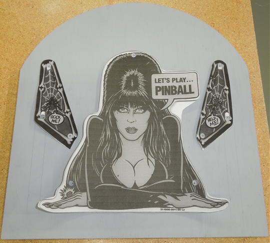
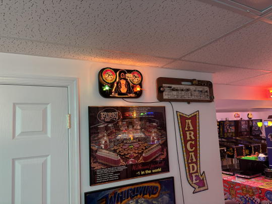
01/12/26: Illuminated wall hanging. After owning this game for 12 years, I finally got a hold of one of the old "Let's Play Pinball" promo plastics. With a pair of cut-down slingshot plastics, I made it into one of my illuminated wall hangings.
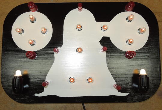
The base is a laminated double layer of ½" plywood cut square on a table saw. Then I used a router and circle jig to get a clean, concentric top arch. At first I was trying to make it in the vague shape of a pinball playfield. But it was starting to look more like a tombstone, so I went with that.
After some priming and sanding, I used the actual plastics to mark mounting holes. Then I switched to copy paper templates because I could stab right through the paper to precisely mark my desired lamp locations.
Copy paper templates.
I drilled mounting and lamp holes. Then I sprayed the base an off-white color and used frisket and my copy paper templates to cut around the white areas. I cut slightly inside the templates such that the white areas are a bit smaller than the plastics. Thus, the white areas are less obvious when viewing the wall hanging straight-on. After weeding the frisket, I sprayed a light coat of the same off-white to seal the remaining mask. Then I sprayed the whole thing semi-gloss black.
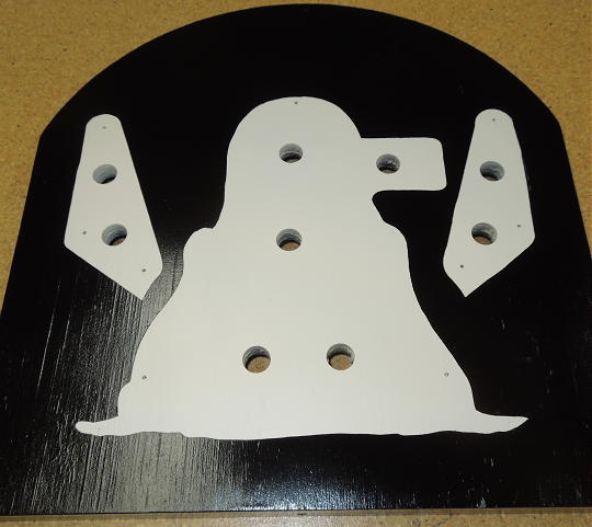
Frisket mask removed.
Before laminating the two layers of plywood, I used a bandsaw to cut away most of the back layer. This creates a center pocket for the lamp sockets and wiring. The top inside edge of the back layer has a slight undercut to grab a screw in the wall.
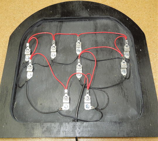
Sockets and wiring.
I used #47 lamps powered by a 5 volt "wall wart". The power pack plugs into a switched outlet such that the wall hanging comes ON with the rest of the room lighting.
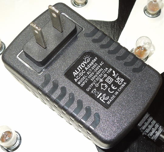
5 volt power pack.
The plastics are supported by Williams standard red star posts.
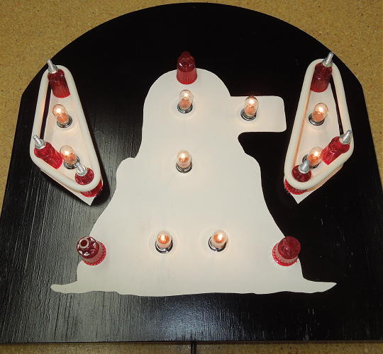
Ready for plastics.
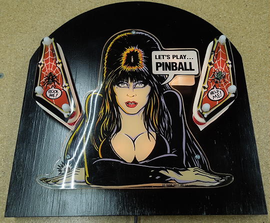
Done!
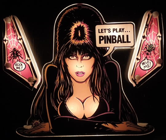
Done!
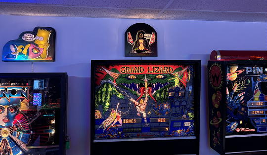
Done!
05/18/26: Illuminated wall hanging. I acquired a second "Let's Play Pinball" promo plastic and decided to build a second wall hanging. Construction was much the same as above, so I won't repeat common details. This time I used a pair of repro speaker cutouts (which were translucent) and a pair of finger puppet "Boogie Men". They're not original, but looked okay in the spirit of things.
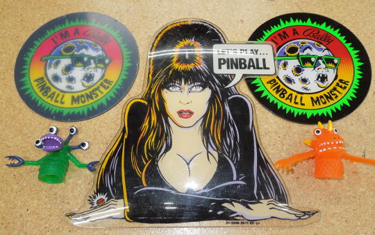
Preliminary design idea.
I notched the right speaker cutout so as to directly illuminate the "Let's Play Pinball" bubble.
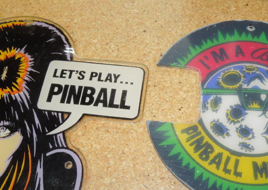
Notched speaker cutout.
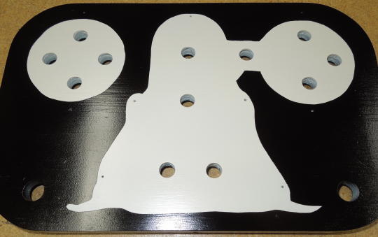
Holes cut and finished paint.
To mount the Boogie Men I used ½" CPVC pipe fittings; a 90-degree elbow with a short length of pipe welded to each end. A 5⁄8" hole in the plywood indexed the elbows such that the elbows fit flush with the plywood. The Boogie Men were a friction fit.
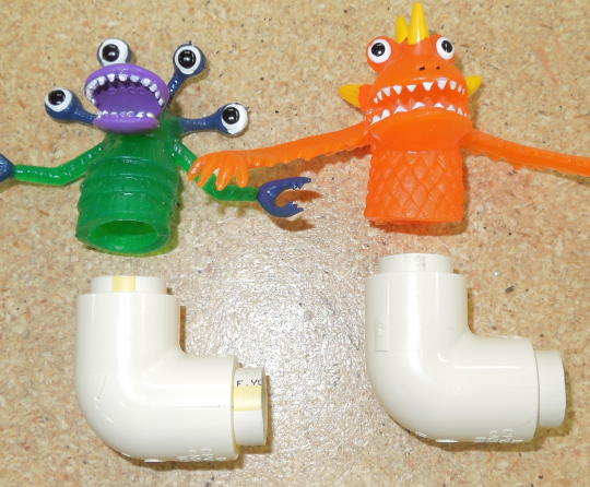
CPVC pipe fittings.
I'm not a fan of LEDs, but for the Boogie Men I used frosted, warm white LEDs because I thought less heat would be better for what ever the Boogie Men were made from. And because I didn't have space for a socket, I took advantage the LED's (hopefully) long life expectancy and hardwired them. The elbows were fixed to the plywood with epoxy. The LEDs were secured in the elbows with a blob of silicone caulk.
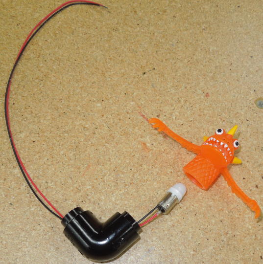
Hardwired LEDs.
So as to layer the center plastic over the speaker cutouts, I used star posts for the cutouts and the slightly taller mini posts for the center.
Ready for plastics.
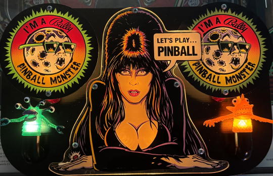
Done!
Done!
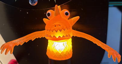
Done!
Done!