

Repair & Maintenance Log
01/22/18: Acquired game.
01/27/18: Installed standard-keyed (751) lock on coin door.
I lightly cleaned the back of the translite. Mainly there was a light splattering of solder that I was able to gently pick away with a fingernail. I guess it has to be said... Move translite - then solder. The game was lit almost entirely with frosted white LEDs. I wanted the game to have a warmer look so I cleaned all the LEDs off the insert panel and installed new incandescent bulbs. I also scrapped the LEDs in the topper. The LEDs in the speaker panel looked okay so I left them as is. I made one translite concession to LEDs. I put a red LED and a green LED in the traffic light feature. The center yellow position looked better with a regular incandescent bulb. The traffic light feature includes a deep bezel that prevents the colored light from bleeding into other areas of the translite.

A comparison... LEDs on the left - #47 bulbs on the right.

A red LED and a green LED in the traffic light feature.
The game had orange flipper rubber. I installed conventional red rings.

New red flipper rings.
02/15/18: The old instruction and price cards were dingy and yellowed so I printed new cards.

New instruction and price cards.
02/18/18: Replaced cracked lift channel at the bottom of the translite glass. New leg bolts. The existing legs otherwise looked pretty good.
03/18: Micro-Shop. I'm calling this a micro-shop job because all I really wanted to do is get the LEDs off the top of the playfield. But while I had all the ramps and plastics out, I cleaned the rubber, wiped down the playfield, applied a coat of wax and addressed a few other items. For the most part the game was clean and working as acquired.
All the top-side LEDs were replaced with appropriate incandescent bulbs except I put some frosted red LEDs in the jet bumpers. I found two bulb inconsistencies between my game and the game manual. The manual specs two #89 bulbs in the upper right corner of the playfield for the Spinout (solenoid #8C). My game has one #89 in the upper right corner of the playfield which is accessible from under the playfield. The other bulb on the circuit is a #906 which is to the right of the Gorbi orbit and only accessible with much playfield disassembly. The manual specs one #89 bulb at the Joyride insert (solenoid #16). My game has no flashlamp at the insert. Instead my game has one #89 in the upper left corner of the playfield which is accessible from under the playfield. And there's another #906 bulb on the circuit which is to the left of the Joyride kickout and only accessible with much playfield disassembly. Or in other words, the Joyride #89/#906 combo on the left mirrors the Spinout #89/#906 combo on the right.
There's a single sided stacked lane guide next to the C rollover. It was missing a spacer and the one that was there seemed too tall. I put it back together with a pair of 1" hex spacers.

Single sided stacked lane guide next to the C rollover.
I'm (mostly) okay with color matched LEDs for insert lighting. In this case the game had color matched frosted LEDs (mostly). I made two changes from the existing scheme. I put incandescent bulbs under all the passenger inserts. The harsh white LED color was too "inhuman" looking. Also the game had white LEDs under all the yellow inserts. I thought they were too harsh so I changed them out to yellow LEDs.

A comparison... LEDs on the left - #555 bulbs on the right.

Done!
04/27/18: Tweeked left habitrail. The Drac catapult fires the ball with such velocity that the ball would often ricochet off the habitrail's downturn, go up the inlane and roll down the outlane. Some previous person appears to have bent the upper right rail to the left and down such that the ball was hitting the downturn of the upper right rail too soon. I bent the rod a bit to the right and up. I'm thinking that the ball should hit the left and right downturns at the same time. It seems to work okay now. I also verified that the catapult has the correct coil. But it seems to be way more powerful than it needs to be. Maybe it's made powerful for dramatic effect.

Tweeking the upper right rail of the left habitrail.
05/20/18: When I acquired this game it already had a remote battery pack in the head and the original battery holder had been removed from the CPU board. I like having my battery packs by the coin door. Opening the coin door is easier than opening the head. The idea is that I'll be better motivated to replace the batteries more often. I extended the battery pack leads, moved the battery pack to inside the coin door and added a connector by the CPU board. I didn't have the nerve to do all this with the game powered ON so I lost my setting and high scores.

Battery connector by the CPU board.

Remote battery pack inside the coin door.
Replaced the power connectors on the two drop target opto boards. On rare occasions the drops targets would become nonresponsive. I believe the power connectors had become loose and unreliable. My Space Station has the same opto board and had similar issues. I replaced all three connectors today.

New power connectors on the drop target opto boards.
The topper was missing the lower right accent decal. I added a new decal from a reproduction decal set.

New lower right accent decal on the topper.
09/22/18: New traffic light plastic. Most Taxies have a decretive traffic light plastic up by the "B" rollover lane. I see so many Taxies without this plastic, I wonder if it's a factory variation. Or maybe it's just easy to remove and forget. My plastics were in good shape so I couldn't see buying a reproduction plastic set just to get the traffic light. Plus I still would not have had the associated bracket. I couldn't find an image good enough to print. So I redrew my own. The best image I found was too pixelated, but it was good enough for a pattern to draw over. I used MS Paint. That's probably a primitive choice. But the traffic light is all geometric shapes so it worked. If you want to use my example, here's my BMP file. If you're printing to a water slide decal, here's the mirror file. It's far from exact, but without a side by side comparison, it's close enough. I had no dimensions to work with. But I printed the file to 57% and it looked about right.

My traffic light image. See links in the above paragraph for the original BMP files.
I made the plastic from 1⁄8" Lexan (polycarbonate). I printed a simple black and white image on copy paper for a template. I stuck it to the Lexan with spray adhesive. I cut the Lexan out on a scroll saw and cleaned up the edges with fine sandpaper. I made a mounting bracket from something I found in my scrap bin. It may have been part of a stand up target assembly. Once I was happy with the shape and fit of my plastic and bracket, I peeled off the protective film from both sides of the Lexan and lightly flame polished the edges.

Plastic and mounting bracket.

Test fit with temporary screw.

Finished Lexan part.
I made the plastic using water slide decal material. I bought packages of both clear and white sheets for this project. I made sure to buy material that was compatible with my inkjet printer. The clear and white sheets look the same before use. So keep the packaging and don't mix things up. I used a Sharpie to write a small "W" on the white sheet I was using. The image is printed on the clear material. Use the best printer settings. The decal goes on the underside of the Lexan part with the adhesive side up. This is why a mirror image is necessary. This is why clear decal material is necessary. The image will be viewed through the decal. Moreover, the image will be viewed through the adhesion interface between the decal and the Lexan. Any imperfections in the decal application process will be glaringly obvious. If you've never done this, make extra parts and practice. The finished plastic shown below was my second attempt.
After printing the image and allowing the ink to dry for a few minutes, I sprayed the image with three light to medium coats of clear acrylic. The first coats should be the lightest. I used Krylon Crystal Clear. The acrylic seals the ink so it won't run when the decal is applied. The acrylic also seals the decal's own adhesive against bleed-through. Without acrylic, the decal becomes a slimy mess and won't easily separate from the backing paper. Thus, the white decal material requires an acrylic treatment even though there's no printing on the white. Only one or two light coats need be applied to the while decal material. If the acrylic is too thick, the white decal will bubble away from the clear decal as the white dries.
The next day I cut out the decal and applied it to the Lexan part as per instructions. I traced around the Lexan part and tried to cut the decal as close as possible to its final shape. I found it easier to line up a cut edge of the decal with a transparent edge of the Lexan. That is, cutting the decal oversized doesn't help. Also, an oversized decal makes it more difficult to blot excess water away from the edges of the plastic. If there is any excess decal material, it can be trimmed with a razor when dry. Think about how the decal and Lexan are oriented. Remember that it's all going together upside down.
While it may be tempting to dunk the decal all at once, I found that this "shocks" the decal, causing it to curl and crack the ink. It's better to slowly and steadily feed the decal into the water, even if part of the decal ends up submerged for an extra minute.
Here's the critical step. The decal must be applied as perfectly as possible. As the decal was soaking for a minute in slightly warm water I applied a decal setting solution to the Lexan. I placed the decal on the Lexan, lined it up and then carefully worked on blotting up excess water and working out any bubbles. Apparently there's some sort of squeegee available for just this purpose. Instead I used a small soft-bristle paint brush. The trick is to work the decal down flat, but don't work it to the point of destroying the decal. Then walk away. The next day I applied the white decal layer in a similar manner.
The white backing has several purposes. It helps protect the printing on the clear decal. It fills in any areas of the clear decal that were supposed to be white. Printers don't print white. And the white brings out the colors printed on the clear decal. By itself the clear decal looks terrible. So you have to finish the whole process before you know if you've made something that looks good. Note that if you're making a plastic with transparent areas, you'd have to pre-cut the white decal accordingly. That wasn't the case with the part I made here.
The final step was to rivet the plastic and bracket together.

Finished assembly.

Finished assembly.

Done!
Traffic Light Update 09/13/24: Six years later... From eBay I found an original traffic light plastic including the bracket. I was on the fence about this swap. I spent a lot of time on my homemade plastic and bracket and I liked how it turned out. Oh well.

Side by side.

Original installed.
11/24/18: The rollunder at the entrance to the right airport arrivals ramp was hanging up so I filed a shallow notch (red arrow) into the adjacent plastic.

Right rollunder.
02/08/19: Fixed Knocker. The knocker stopped working and I was getting some bad readings at Q7 on the MPU board. I was able to get the knocker to fire by grounding the collector of Q7. That is, everything downstream of Q7 (including Q5 on the aux driver board) was working. The next day the knocker was back and Q7 seemed okay. I hate intermittent problems. But I pulled the MPU board anyway and replaced Q7. While I was at it I replaced the pre-driver Q3. In all my years of owning System 11 games, I think this was the first time I pulled an MPU board. That's a lot of connectors! Once I got Q7 off the board, it still tested good. Damn! It's all back together and the knocker works fine. We'll see... All this happened right after my epic (for me) 14 million point game. I lost my high score when I disconnected the remote battery pack.

New Q7 and Q3.

Never again.
02/20/19: New Spinout Ramp. This may have been a waste of effort. The old ramp looked okay and played okay. But it did have a lot of cracked and blown out mounting holes. I don't find much consistency with the skill shot on this game. I thought that a new unbroken ramp might be more ridge and offer an improvement in ball control. I don't see that it made any difference.
This wasn't quite plug and play. Before attempting to install the new ramp I pre-tapped all ten screw holes. I used a cut off disk in a Dremel to grind a cutting edge in one of each type of assembly screw. Or in other words I made my own self-tapping screws. Then I used the screws to pre-tap all the holes.

Homemade taps.

Tapping a mounting hole for the micro switch.

New ramp looks about the same as the old.
I replaced the plunger sleeve. That may have helped, but not much. This game had the stiffest plunger spring I've encountered. I put in a slightly less stiff spring. This seems counter intuitive, but finesse seems to help more than brute force.
Some previous person shimmed up the bottom of the habitrail with a pair of washers. I took the cue and doubled up the washers. I filed each washer to a slight oval shape to fit in the playfield slots. The washers effectively reduce the slope of the habitrail which preserves more energy from the plunger. While working on the habitrail I also notice a broken weld along the lower right rail. The loose rail may be inconsistently absorbing ball energy.

Shimming up the habitrail with washers.
03/22/19: Reinstalled habitrail after having it welded by Fabrication Unlimited (www.fabunlimited.com). This business had been promoted on Pinside. It's the second time I've used their service and have been happy with the work. Some plating was lost at the weld point, but it still shined up reasonably well. Plus it's all hidden by the limo plastic. In any event, the repaired habitrail had no noticeable effect on my inconsistent skill shots.

Broken weld.

Good repair weld, bad picture.

Done.
01/13/24: I've had a long-standing problem with balls bouncing back from the lock hole. Anything but the weakest of shots wouldn't stick. I got some low-profile "Dead Drop" foam from someone called SONIC on Pinside. I put a patch of it on the backstop and now every ball sticks in the hole.

Dead Drop foam at the lock hole.
11/29/25: All six drop targets were scoring intermittently. The problem seemed to be a low 10 volts at the opto boards. Starting at the power supply, I measured my way down through all the intervening connectors including J1 on the power supply board and J2 & J16 on the interconnect board. But, by the time I got down to the opto boards I was back to measuring 12 volts and the targets were scoring again. My "fix" for the time being was to simply reseat the aforementioned connectors. J2 was particularly loose. We'll see..
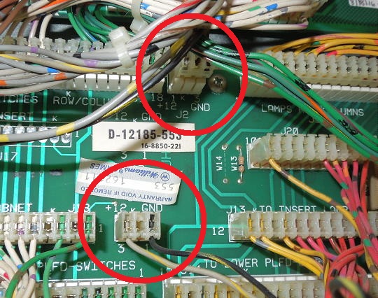
J2 and J16 on the interconnect board.