

Repair & Maintenance Log
07/03/07: Acquired a complete NOS plastics set off eBay. I knew I would own this game someday.
04/05/08: Acquired Game.
04/05/08: Cleaned flipper coil sleeves. Re-soldered left lane change switch. Adjusted lock down bar.
04/05/08: Added remote battery backup. Instead of permanently soldering some sort of remote battery setup to the CPU board I made battery place-holders from ½" dowel. This method requires no board modifications. And no connectors are needed between the board and the battery pack. The battery pack is from Great Plains Electronics. I like that the pack is fully enclosed. I don't like that it has an integral ON/OFF switch. I set the switch to ON and put a blob of silicone caulk over it. The battery wires are mounted to an end of each dowel with a screw and crimp terminal. The screw head becomes the "battery terminal". Don't forget to account for the height of the screw head when figuring the length of the dowel. Also shown is a plastic tool I got from Home Depot. The tool is for pulling large inline fuses, but is also great for pulling AA batteries.

Battery place-holders and remote battery pack. Note the blob of silicone over the battery pack switch.
The CPU board shows how each battery must be oriented, but does not show the location of +4.5 volts. Before removing the old batteries I used my volt meter to confirm that the lower-left terminal of the battery holder is +4.5 volts. The orientation shown here is correct for most System-11 CPU boards. Grand Lizard is at least one exception. Grand Lizard and the previous System-9 CPU boards (along with their battery holders) are oriented 180 degrees from that shown here.

Dowel sticks in place.
01/15/12 - Battery pack update: I rewired all my remote battery packs with 8' leads. Instead of placing the battery pack in the head, I drop it down into the body and place it next to the cash box. Opening the coin door is easier than opening the head. The idea is that I'll be better motivated to replace the batteries more often.

Remote battery packs with 8' leads. Scruffy gives each assembly a quality control check.
04/10/08: Some new parts arrived today. Replaced translite (old translite was chipped). Replaced flipper buttons (old buttons were red on one side and blue on the other). Replaced playfield glass top rail (old rail chipped). New plumb bob (old plumb bob was missing). Also received a ring kit and a bottom drop target decal (old decal missing), but I'll save all that for when I tear down and clean the playfield.
![]()

A few of the old parts that got the boot.
04/19/08: The apron had a card and decal from "Rockville Home Amusements", a defunct retailer. I cleaned up the apron and printed off a new price card. Also began cleaning the hardened residue of ancient tape from the display panel. I'm guessing someone thought the game was too loud and taped over the speaker cutouts. Ugh. So I'm picking away with GooGone and a fingernail. This is going to take a while.

Apron cleaned up with new price card.
05/08: Ramp repair... The lone vacuum-formed ramp was the scariest part of the game. The base was cracked along both sides. There was a crack above the flap. The mounting holes were cracked. There was a hack patch over the missing right side. And all this was held together with what appeared to be hot glue. I decided to follow Ed Cheung's ramp repair procedure for this project. Check out Ed's Space Shuttle restoration at... www.edcheung.com. Shown below is what I started with. The rectangular piece was a hack patch for the right side. Check out that piece on the far right. That's an original piece that I found in the bottom of the cabinet. It will save me the trouble of having to recreate the right top flange of the ramp. Fortunately hot glue does not bond to plastic so it was easy to clean off the glue and disassemble the pieces.

Existing ramp fragments.
I picked up this "plastic weld" two-part epoxy at the hardware store. Then I read the fine print on the back and it said it might not bond to polyethylene or polypropylene. I have no idea what that means. I tested the epoxy on the back of the ramp. It seemed to soften the surface of the plastic, bond and harden. I think it will work. We'll see...

Plastic weld epoxy.
Next I grabbed some rough sandpaper and thoroughly scuffed up the underside of all the pieces. This whole area will be covered with mesh and epoxy. But first I mixed small batches of epoxy and "tack welded" all the pieces back together. That "arm" at the bottom of the picture is the piece I found in the bottom of the cabinet. But there's still a substantial chunk missing from that side. Note also that there are several hairline cracks around the bottom mounting holes.

Tacking the pieces together.
I decided to utilize that rectangular patch that was hot glued to the ramp. I don't think it's exactly the same kind of plastic. But it's a good color match. If I'm careful I should be able to pull this off without having to repaint the inside side of the ramp. I put a piece of masking tape over the part and traced out the shape I needed. Then I used a Dremel and sharp knife to carve it to shape.

Trimming the patch.

The patch tacked in place with the rest of the pieces.
Next I covered the underside of the ramp with drywall mesh. The mesh has some stick to it so it more or less stays in place by itself. I overlapped the pieces so there are at least two layers over every crack. Then I covered it over with epoxy. The epoxy has a working time of about 5 minutes so I only covered about 2 or 3 square inches per batch. I mixed it up and carefully worked it into the mesh with a toothpick. I cut the mesh around the rivets so it would lay flat. But then I epoxied right over the rivets. The ramp flap is in good shape so I'm not worried about having to get the rivets out. After the epoxy is fully cured I'll come back and trim the edges and re-drill the mounting holes. The epoxy fumes are nasty.

Mesh and epoxy.
I noticed a hairline crack where the ramp is notched for a playfield flash lamp. Since this is a visible area I carefully applied mesh and epoxy to just the underside of the flange.

More mesh and epoxy.
The plastic around the drop hole at the top of the ramp was only paper-thin and there was some chipping around the edges. So I added some mesh and epoxy here too.

More mesh and epoxy.
The left outer wall of the ramp is slightly visible from the playfield, so I needed to paint over my repair. I wanted to paint as little of the ramp as possible so I masked off my repairs with painter's tape. First I tried semi-gloss black from a rattle can. But that didn't look right so I shot it with flat. Flat is the way to go. I also painted the underside of the ramp as well as the right outer wall. Although these areas are not visible, the black backing helps prevent ambient light from shining through the cracks.

Taped and ready for paint.

Finished ramp.
Finally, I cleaned up the ramp with some Novus and reinstalled. The picture below shows the ramp entrance from the player's perspective. It's a bright, busy area and the eye is not drawn to the dark area of the repair. From a playability point of view, a solid, unbroken ramp does not absorb as much of the ball's momentum so it's easier to get the ball up to the diverter.

Done!
The upper mini-playfield is in good shape. But I did notice some stress fractures around the habitrail mounting holes on both sides. So I applied some mesh and epoxy around the holes on the underside. Since the mini-playfield is translucent, I only applied one layer of mesh and a light coat of epoxy.

Upper mini-playfield with a bit mesh and epoxy.
05/08: Shopped game. The games I've bought have been pretty clean to start. After Cyclone, Space Station is only the second game I've completely torn down and shopped. But Space Station is even more complex and intimidating. I began by removing the upper mini-playfield and all the top-layer ramps and plastics. From there I didn't have the nerve to strip the whole playfield at once. So I just worked one section at a time moving clockwise from the top left corner. All in all I disassembled and cleaned the mechanisms, cleaned everything else, rebuilt the flippers, replaced the flipper bats, cleaned and waxed the playfield, changed all the bulbs from #44 to #47 and replaced all the rubber.
Below is the upper playfield after I've stripped away all the top-level components. For each part I remove from the playfield I immediately reinstall the screws. I suppose this is more time consuming, but at the end of the day every piece of hardware is right back in its original position. It makes it much easier to remember how everything goes back together.

Upper playfield partially disassembled.
I spun out a lot of T-nuts thanks to old rock-hard thread lock. Fortunately, I was able to get them all with vice-grip pliers. After cleaning up the threads with a tap and die set I was able to reform and reseat the T-nuts.

Grabbing a T-nut with vice-grip pliers.
The Space Station diverter can become confused if the optos are dirty. The picture below shows the diverter opto board. I cleaned the optos with Windex and Q-tips. Note the disk with the half-rim. The half-rim in combination with the optos allows the game to accurately index the diverter. Note the pin on the motor shaft and the corresponding notch on the disk.

Opto board and disk.
Below is the disk right-side-up and mounted on the shaft. Note the tab on the top of the disk that corresponds with a notch on the bottom of the diverter. Next up is a spring. Then the diverter is slipped over the spring and disk and secured with the nut. The nut and spring allow the diverter to be vertically adjusted to properly line up with the surrounding ramps.

Disk and spring.
I'm not a big fan of rebuilding jet bumpers. But two of the three bodies were busted up so here we go... The picture below shows the only real problem with the playfield. There's a big wear spot over the top bumper and a smaller spot by the lower bumper. It's obvious where the factory Mylar ends. But playfield touchups are beyond my scope at this point. Plus the wear spots are not visible from any normal viewing angle. So for now I just added some Mylar patches. The picture also shows damage to the top and left bumper bodies. One of the ring and rod assemblies was also mangled.

Jet bumpers before rebuilding.
The old lamp sockets have ribbon-like leads that make nice 90 degree bends. That's important so the bulb stays low in the bumper body and doesn't melt the bumper caps. The new lamp sockets have stranded wire leads that don't bend and hold their shape well. I saw this zip-tie trick on the Internet somewhere. It holds the wire to shape and lets the socket sit low in the body. Note also that the new bumper body is a bit taller for better bulb clearance. My caps are already melted anyway. But I don't think I'll replace them as they're all covered by playfield plastics.

Old and new and lamp sockets and bumper bodies.

What's wrong with this picture? Yes, I already soldered in the new lamp socket and reassembled the coil mechanism. I'm done for today.
Below is the upper right corner of the playfield ready to have the top-layer components reinstalled. I included this picture because it shows several components not normally seen including both ball poppers, the diverter mechanism and the right ball dock eject lane.

Upper right corner of the playfield.

New drop target decal.
After removing the right ball guide I noticed a "mystery hole" by the right flipper bushing. Then I discovered what I called the "flipper bushing deluxe hardware kit". Someone decided to re-drill and tap the flipper base plates for #8 screws. But they didn't remove the plates; they just drilled right into the playfield. I guess they only had three #8 screws so they switched to sheet metal screws. But I guess they only had two sheet metal screws and then ran out of screws all together. No two screws are alike. Two screws are stripped. Fortunately only one hole penetrated the surface of the playfield. It's small and hidden under a ball guide. This is the only destructive hack I've found in what is otherwise a decent playfield.


Flipper bushing deluxe hardware kit.
Some previous person also got carried away with tightening the ball guides and sort of squashed the black plastic spacers. Note the warped slingshot plastic. I cut the clips off the top spacers and replaced the machine screws with flat washers and post studs. Now the slingshot plastics can float instead of being rigidly fastened.


Post studs for the slingshot plastics.
The plastics on this game had some chips and warps and were slightly yellowed. Nevertheless they were perfectly respectable for a game of this age. But I decided to replace them because NOS plastics sets are so readily available. They routinely show up on eBay for not much money. Why? Do the plastics on this game never break and there's no demand? Did someone at Williams over order? In any event, I decided to protect my new plastics set with a full Mylar undercoating. I started with a 1'x3' sheet of Mylar. I pealed off the backing and taped it sticky-side-up onto a glass coffee table. Then I placed my plastics right-side-up on the Mylar. The 1'x3' Mylar sheet was more than enough material. Then I flipped the whole thing over and used a razor blade to rough cut out all the pieces. Using a finger nail, I carefully burnished the Mylar onto each piece (this is a good project to do in front of the TV). Finally, I used fresh razor blades and Xacto knife blades to trim the pieces and cut out all the mounting holes. I did not Mylar plastics that were mostly transparent such as the bumper cap plastics and that second-tier plastic between the mini-playfield and ball diverter.
Below is a new plastic (top) and an old plastic (bottom). I didn't have a rivet press so I used machine screws and nuts to reattach the flash lamp lenses. The old plastic shows some underside rub marks that I'm hoping the Mylar will prevent.

A new plastic (top) and an old plastic.
That about wraps up this shop job. Here is my parting advice... After installing each habitrail, ramp or other major assembly, flick on the game and carefully check for ball hang-ups as well as proper switch and light operation.
The left picture below shows the habitrail for the center ball popper. I assumed the flat washer should go between the wireform and the screw. Wrong. The flat washer needs to go under the wireform. Otherwise the wire ring is too close to the playfield and the ball is blocked from entering the popper. I did not discover this until after the mini-playfield was installed. The mini-playfield had to come back out. The right picture shows another ball hang-up. In this case a ball became trapped above the left orbit roll-under because the switch linkage hung up on my new plastic. I had re-installed the mini-playfield for the second time before discovering this one. Rather than remove the mini-playfield again, I tediously whittled away at the plastic with an Xacto knife.


Reassembly errors.
05/08: Replaced some incandescent bulbs with LEDs. LED technology has reached the world of pinball. Several pinball parts suppliers are now developing LEDs that plug right into a standard incandescent socket. They come in all shapes and colors.
One of Space Station's niftiest features is the dual GI circuit. During multiball, all the regular GI turns OFF and a second circuit of green GI turns ON. This should be a really cool effect. But it's not because the green GI is pretty dim. The green light is produced by fitting regular white bulbs with green bulb condoms. Problem is that bulb condoms block out most of the bulb's light energy.
But a green LED is not filtered white light. A green LED actually produces green light. At least I think that's how it works. In any event, the LEDs are much brighter. So I got me a bag of LEDs to try on my Space Station. I got them from... www.bcspinball.com
Below are pictures of a slingshot. The top lamp is a conventional incandescent with bulb condom. The bottom lamp is an LED. It's hard to show in the pictures, but the LED is much brighter. The right picture shows the same area with the plastic installed. This picture more clearly shows that the area around the bottom of the plastic is a lot brighter.


Frosted green LED versus incandescent lamp with green bulb condom.
Space Station also features blue bulb comdoms for the lower rollover guides and amber bulb condoms for the upper rollover guides. I replaced these with colored LEDs as well. Additionally, I put red LEDs under the bumper caps. Every other lamp on the playfield is a conventional incandescent bulb (although I did replace all the #44 lamps with #47 lamps).

Condition green.

Upper-left playfield area.
The space station depicted on the game's translite features six windows around the perimeter of the station. The "windows" are just holes punched through the translite. Each window is backed by a controlled bulb. The bulbs flash and perform various chase effects. Since there's nothing to diffuse the bulb, I thought the effect was a bit harsh. And the translite is not particularly colorful. So I replaced these six bulbs with more frosted green LEDs.


Six frosted green LEDs.
Total LED inventory for this project:
25 green #44-style LEDs for the playfield GI
6 green #44-style LEDs for the insert panel
4 amber #44-style LEDs for the upper rollover guides
4 blue #44-style LEDs for the lower rollover guides
3 red #555-style LEDs for the bumper caps
04/01/10: New legs, bolts and levelers.
03/04/12: GI to the insert panel is divided between two circuits. The left side of my insert panel has always been dimmer than the right. Eventually I noticed a GI connector on the interconnect board that was burning itself up. The interconnect board is on the left side of the head and provides all the connection points between the insert panel and the rest of the head circuitry. The board was toasted in the area of J1. The J1 area was also the victim of a previous repair. I replaced the two sets of GI header pins at J1 and jumped the two damaged center traces. Then I replaced the connectors. Now both sides of my insert panel are bright and the connectors run cool.

The J1 area of the interconnect board was burning up.

The two center traces at J1 needed to be jumped.
03/18/12: New playfield glass.
03/24/12: Installed standard-keyed (751) lock on coin door.
11/19/15: All column 6 (yellow/blue wire) lamps were out. I "fixed" the problem by reseating connector J7 on the CPU board.
11/17/17: The three drop targets were non-responsive. They went down and didn't come back up. This turned out to be an intermittent problem and I'm pretty sure it was caused by a loose power and ground connector on the drop target opto board. If the problem reoccurs, I'll address the connector.
05/20/18: Replaced the power connector on the drop target opto board. My Taxi has two of the same opto boards with similar issues. I replaced all three connectors today.

New power connector on the drop target opto board.
08/15/19: The rod and plumb bob were missing when I acquired this game. Only took me eleven years to get around to it.

New rod and plumb bob.
01/15/23: Display Fix. The player one glass had always been sagging against the display panel. Some previous person replaced the player one glass, but didn't do a good job. The leads are misaligned and not properly bent. And the standoffs were missing. I didn't have good access to add back the lower middle standoff, but I added back the two upper standoffs. The glass was too misaligned to get good adhesion, so I *very* carefully clamped down the glass and glued it to the standoffs with some black silicone gasket adhesive. If my "repair" fails, the glass will just droop back down as it's been for the last 15 years.
I also added back the missing player one display masking. I got these from Marco. The window openings are always ¼" too narrow and need to be trimmed out. So the player one glass is still not quite square and level, but I guess it looks a bit better than it did.

Player one glass glued to the new upper standoffs.

Display masking.

Done.
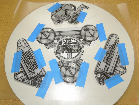
02/11/26: "Condition Green" illuminated wall hanging. This project started with a few promo plastics and some old, leftover playfield plastics. The idea was to build up the project in layers similar to a playfield.
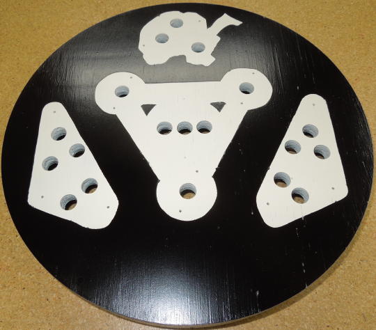
After arranging the plastics to my liking on a 12" square, ½" piece of plywood, I used a bandsaw to cut away some unneeded mounting appendages from the playfield plastics. First I used the modified plastics to mark mounting holes. Then I switched to copy paper templates because I could stab right through the paper to exactly mark my desired lamp socket locations.
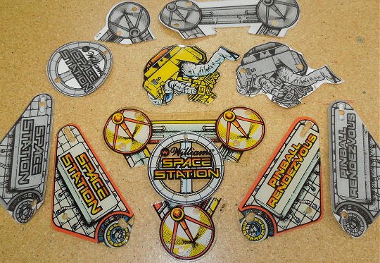
Plastics and templates.
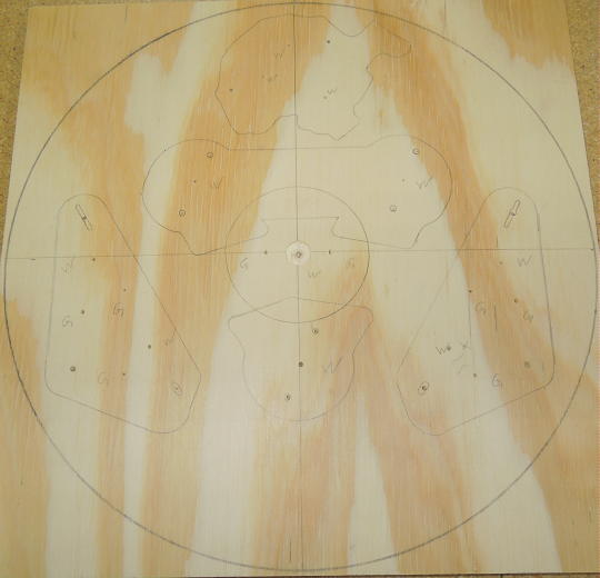
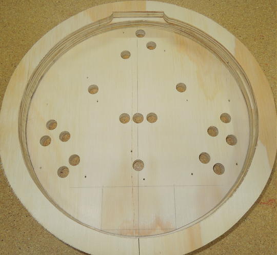
Layout with marked mounting hole and socket locations.
Before drilling out the center socket hole, I used the mark and a router with a circle jig to cut the plywood square into a disk.
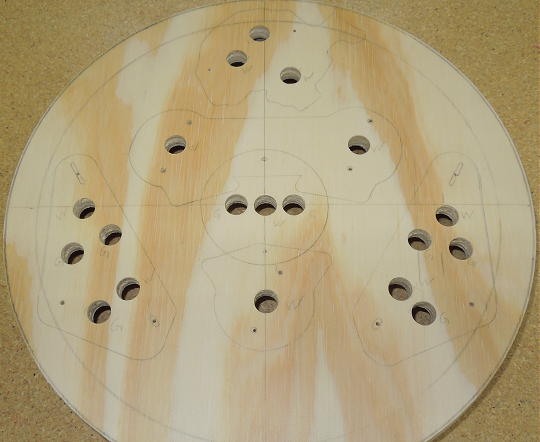
Disk cut and holes drilled.
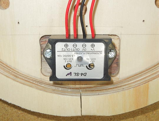
I've incorporated #455 lamps into similar wall hangings. But for this project I was going to need a more coordinated approach to initiate "Condition Green". From Amazon I found a dual output alternating flasher module. In typical Amazon fashion, the product appeared under multiple brand names, multiple model numbers and multiple descriptions. It appeared to be directed primarily toward implementing emergency vehicle lighting. I liked that it had long duration times (up to 15 seconds). I liked that it was asymmetrically adjustable such that Condition Green could appear only briefly. I liked that it could operate down to 5 volts.
Per spec, the module had 25-turn potentiometers. That might be good for short duration fine tuning, but it was tedious at longer durations. Ultimately, I adjusted the module such that Condition Green was active for about 5 out of every 15 seconds.
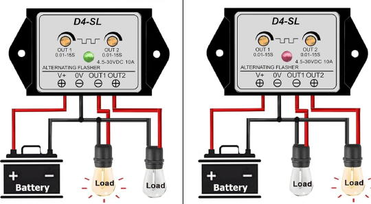
Dual output alternating flasher module.
Typically I'd add a back perimeter layer of ½" plywood to create a pocket for the sockets and wiring. In this case I added two layers for the height of the control module. I added a slight under cut to the inside top edge of the back layer to grab a screw in the wall.
Rough-cut mid and back layers.
That still wasn't enough, so I routed a ¼" recess into the back of the front layer to accommodate the control module.
Test fitting the control module.
The mid and back layers were rough-cut on a bandsaw. After gluing up each layer, I went over the outside edge with a flush-cut trim bit so the mid and back layers perfectly matched the concentricity of the front layer.
After some priming and sanding, I sprayed the base an off-white color because playfields tend to age to off-white. Then I used frisket and my copy paper templates to cut around the intended white areas. I cut slightly inside the templates such that the white areas were a bit smaller than the plastics. Thus, the white areas were less obvious when viewing the wall hanging straight-on. After weeding the frisket, I sprayed a light coat of the same off-white to seal the remaining mask. Then I sprayed the whole thing semi-gloss black.
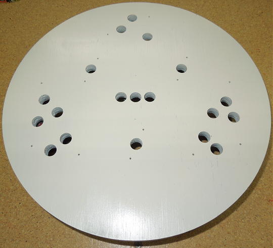
Rust-Oleum Heirloom White.
Templates taped over frisket, ready for cutting.
Semi-gloss black applied and frisket removed.
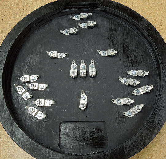
Densley packed lamp sockets with a solder lug on each bracket.
The project included three circuits. The "astronaut circuit" comprised three #47 lamps and was connected directly to the power supply and always illuminated. The white circuit comprised eight #47 lamps and was connected to one output of the control module. The Condition Green circuit comprised eight frosted green LEDs and was connected to the other output of the control circuit. The combination of #47 lamps and frosted green LEDs matched the configuration of my Space Station pinball machine.
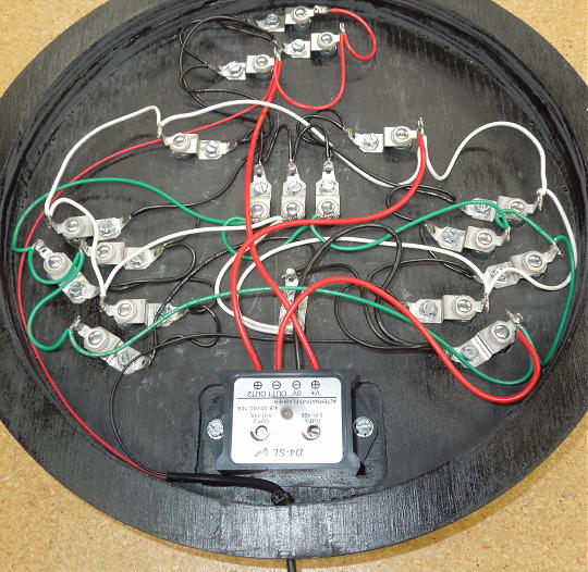
Final wiring.
The project was powered by a 5 volt "wall wart". The cord was extended to about 8'. The power pack plugged into a switched outlet such that the wall hanging would come ON with the rest of the room lighting.
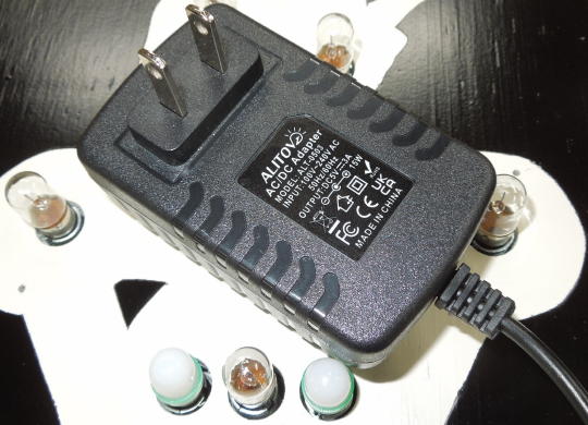
5 volt power pack.
The plastics were supported by Williams blue jewel and narrow posts.
Ready for plastics.
The center promo plastic was slightly elevated from the other plastics with a pair of cutdown blue narrow posts. The lower plastics had a corresponding pair of mounting holes tapped 6-32.
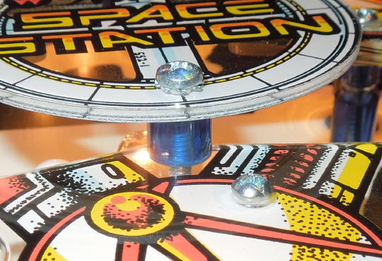
Center plastic mounting.
Done!
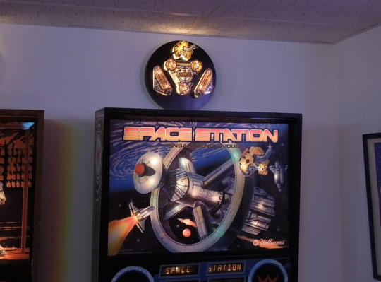
Done!
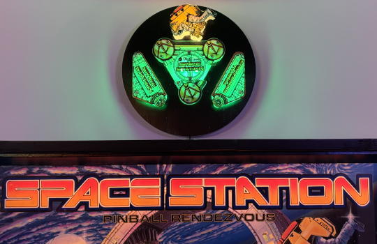
Done!