

Repair & Maintenance Log
08/11/24: Acquired game.
08/24/24: Installed one of my standard-keyed (751) locks on the coin door.
08/26/24: Printed new instruction and price cards to replace the custom cards that were in the game.

Fresh instruction and price cards.
08/28/24: New backbox bolts and washers (because I left the old ones at the seller's house). The existing legs and hardware were kind of grubby. I cleaned up the legs with some Scotch-Brite and Mean Green and reinstalled with new bolts and levelers.
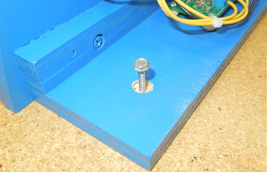
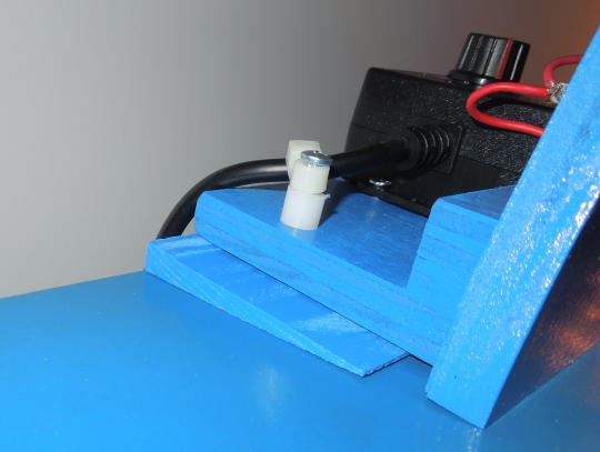
08/28/24: Added remote battery backup. Instead of permanently soldering some sort of remote battery setup to the CPU board I made battery place-holders from ½" dowel. To me this is the most universal solution because no board modifications or specialized connectors are needed. The place-holders will work with any unmodified board. The battery wires are mounted to an end of each dowel with a screw and crimp terminal. The screw head becomes the "battery terminal". Don't forget to account for the height of the screw head when figuring the length of the dowel. I wired the battery pack with 8' leads. Instead of placing the battery pack in the head, I dropped it down into the body and placed it inside the coin door. Opening the coin door is easier than opening the head. The idea is that I'll be better motivated to replace the batteries more often.
My procedure was less important with this game because some previous person had already lopped off the original battery holder and plopped on something else with double-sided tape. If I ever have to pull the board, I'll replace it with a proper battery holder. Normally the lower-left terminal of the stock battery holder would be +4.5 volts and the upper right terminal would be ground. Grand Lizard is at least one exception. Grand Lizard and the previous system 9 CPU boards (along with their battery holders) are oriented 180 degrees from every other system 11 CPU.

Battery place-holders.

Battery pack inside the coin door.
11/24 - 11/25: Shopped game. A whole year? Really?
What I have learned over the decades is that I can never have too many teardown pictures. I take pictures of the area I'm about to disassemble. Then I record the type and location of hardware as it's removed. I record how any flat washers are layered. I measure each post before removing it. I take pictures of any connectors and record how wires are routed. Even if I'm convinced that something was assembled incorrectly, I still meticulously record how I found it. I took over 200 pictures just during the topside teardown.

An example of a before picture.

One of many after pictures showing the type and location of removed hardware.

Measuring a post before removal.
I should have also measured all the old rubber rings as I removed them (ominous foreshadowing).
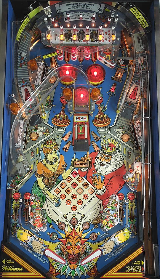
The picture below shows the extent to which I stripped the top of the playfield. That was good enough to clean everything up with naptha and Novus 2. Here's where it got weird. The game appears to have non-factory Mylar. It was in great shape. The underling playfield finish and inserts were in great shape. But several areas outside the Mylar were somehow worn to the wood and painted white. I have no idea how such surgical destruction could have occurred to non-wear areas. Fortunately, the playfield doesn't look terrible when assembled.

Topside disassembled.

WTF?
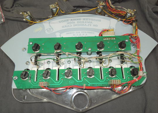
The picture below shows the extent to which I stripped the bottom of the playfield. That was good enough to get to work on cleaning the inserts and bulbs. I could unscrew some of the lamp boards for cleaning without removing them altogether. Any discolored or otherwise suspect bulbs were replaced with new #47 or #555 bulbs.

Bottom disassembled .
I don't like disassembling/assembling mechanisms in place. And I don't like desoldering/soldering coils in place. So I now just clip the coil wires and add connectors. First I clip the wires. Then I remove the mechanism. Then I add a playfield-side connector. The mechanism-side of the connector is added at the bench as I'm servicing the rest of the mechanism.
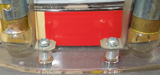
I used the knocker assembly as my guide to establish a coil connector standard. I use three-position connectors with .093" pins. A female housing with male pins goes on the coil side of each connection. The power wires go toward the pointy side of the connectors and the control wires go toward the flat side of the connectors. The center position is left empty

Male coil connectors added under the playfield.
Below are some of the cleaned mechanisms with coil connectors and new sleeves. All the plungers were gunky. I'm thinking they had been previously lubricated.

Clean mechanisms with connectors.
The jet bumper parts were in good shape except for one broken body. Aside from cleaning, the only new parts I added were connectors, bodies, coil sleeves and LEDs.
Jet bumpers are one place I'll make a concession to LEDs. It isn't that I like LEDs, it's that I hate bumper sockets. So I take advantage of the LED's (theoretical) long life expectancy and hardwire them into the game. These LEDs don't necessarily like being soldered on. I'm quick with the soldering iron. Then I retest the LED and make sure the LED hasn't come loose in its bayonet housing.

Frosted red LEDs for the jet bumpers.

LED installed in a new jet bumper body.
Next was cleaning the cruddy, gunky drop target assemblies. Attention n00bs: don't lubricate coil sleeves! The two left-side assemblies were in good shape. All I did was disassemble and clean everything, reflow the header pins, replace the coil sleeves and add coil connectors. The right-side assembly was a bit more work with mangled header pins and lots of missing washers and e-clips. Anything under the playfield within striking distance of the prop stick was beat. Thus, the right-side assembly also received new header pins and some replacement hardware.

Mangled right-side drop target assembly.
I always prefer to keep original decals. Reproduction decals never have the right sheen. Fortunately, all the drop target decals were in good shape. They cleaned up with soap and water and some Novus 2. It seems to me that the decals should have been applied higher up on the targets. Oh well.
One out of the nine targets was cracked (from the right-side assembly, of course). So I did have to move one decal. I carefully removed the decal with a heat gun. I cleaned off the old adhesive with Goo Gone. And I applied the decal to a new target with 3M 467MP transfer tape.
Replacement targets often have defects such as flash, warps and shape imperfections. I picked the best one I had on hand. And I assembled and tested it out before risking my decal.

Clean decal ready to go on a new target.
All three of my drop target assemblies had the same arrangement of targets with the decal part numbers in numerical order. So that's how I put them back together.

Drop target decals in numerical order.

Done!
My experience with these system 11 drop target assemblies is that the opto board power connector is a point of failure. They're held with only three pins. 37 years later, they're loose. So I replaced the power connectors for all three opto boards. Also, note that the new header pins were trimmed so as to not catch on the fingers of the reset plate.

New power connector on the right-side assembly.
My left flipper coil was missing a diode. I was about to tack in a new diode when I noticed that the same diode was already broke on the right coil. Then I suspected a production issue and just replaced both coils. The replacement coils had a "tighter" diode arrangement.

Existing coil (left) compared to a replacement coil.
When rebuilding flipper mechs I like to install the new flipper bushing first. But then the assembly becomes awkward to handle. How about a Flipper Mech Rebuild Rack? The FMRR - otherwise known as a scrap of plywood with left and right flipper bushing clearance holes. The FMRR keeps the flipper base flat and stable and gives me something more substantial to hold while installing the remaining components.

The FMRR.

Flipper base screwed down with bushing installed.
I had a flipper rebuild kit on hand so I pretty much replaced everything. The new capacitors were frustrating because the leads were shorter than the originals. Newer kits integrate the cap head screw and crank washer. I've had issues with these pulling apart, so I reuse the old cap head screw and discrete crank washer (red arrows).

I reuse the old cap head screws and crank washers.
While I had the mech disassembled, I drilled the EOS switch bracket for an extension spring. I'm not a good enough player to tell the difference between the older compression springs and the newer extension springs, but whatever. I also turned the coils so the diodes and wiring were away from coil stop impacts.
I took an old flipper (black in this case) and cut away most of the bat. I used what remained to align the pawl and bushing. Then I could get a head start on adjusting the EOS switch before putting the mech back in the game.

FMRR with pawl/bushing alignment.
I also got a new set of flipper bats because the existing bats were the up-side-down "W" bats. That said, I didn't reinstall the slingshot and flipper mechs until the end. There was still a lot of up and down with the playfield. No sense in adding back that extra weight until I had to.

New bat (left) vs. existing bat.
The underside of the playfield had an excessive number of blown-out mounting holes. The mechanisms were mounted with self-tapping screws that seemed to have overly aggressive cutting edges. This may have been good for initial assembly, but now the holes were worn out. My usual glue and toothpick plugging solution was hit and miss because the cutting edge could immediately wreck the toothpick. Compare this to a screw from one of my older system 11 games that had no cutting edge. For future servicing I got myself a stash of non-self-tapping screws. Oddly enough, I found exactly what I was looking for at Home Depot called Teks, part #21301.

Older system 11 screw vs. Jokerz! screw.

Teks, part #21301.
The eject hole shield and corresponding microswitch bracket had spacers. I had not seen this before, but confirmed that other Jokerz! are similarly configured. However, I have not found any reference to these spacers in the manual or parts catalogs.

Eject hole shield and spacer.

Shield and microswitch spacers.
The only under-playfield mechanism I didn't mess with was the motorized ramp. It was reasonably clean and worked well. So I left it be.
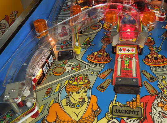
Some of the BET lane guides were broke and all the star posts were in various stages of not great. So I replaced all that with new parts.

All new lane guides and star posts.
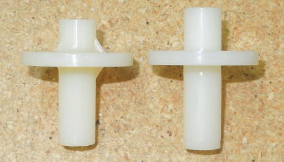
On a whim I bought a new spinner from Planetary Pinball. But it was so well balanced it would just randomly stop wherever. So I ended up going back to the existing spinner, which stops upright as it should. Trying to replace parts that don't need to be replaced can be more trouble than it's worth.

New non-working spinner (top) vs. the existing spinner.
The "Spots Card" decal for the upper left kicker was curled and misaligned. I carefully removed the decal with a heat gun. I cleaned off the old adhesive with Goo Gone. And I reapplied the decal with 3M 467MP transfer tape. Before reapplying the decal, I scanned it at 300 dpi over a one inch grid.

Before.

After.
I keep a stash of machine screws and wingnuts on hand for installing metal posts without resorting to pliers. The wingnut jams against the post and gives me something to hold while tightening the under-playfield nut.

Wingnuts for installing metal posts.
I went with a conventional white ring kit including red (per spec') flipper rubber. Unfortunately, the Jokerz! manual does not include ring mapping information. And I failed to measure the old rings as I removed them. But I found some helpful hints on the Internet to get me started and made my own main playfield ring map as I went. I'm not saying it's officially correct, but it worked for me. I didn't bother mapping the smaller bumpers and sleeving because I could figure all that from my teardown pictures. I omitted mapping for the upper mini-playfield. That'll be dealt with later.

Main playfield ring map.
Based on my game and pictures of other Jokerz!, there should be a tapered bumper (23-6579) to the right of the left ramp. But that's not included in the Rubber Parts list. I didn't have a new one on hand, so I just cleaned up the existing one.

Tapered bumper 23-6579.
The plastics on this game were decent. But Planetary Pinball had reproductions. And since the game was already apart, I bought a new set. There was a lot of riveting, which I thought would be a good warm up for replacing the upper mini-playfield. And there were some anomalies aside from the usual trimming and fitting. Maybe it was me, but I didn't think these plastics were as flexible and forgiving as what I previously experienced with plastics from CPR.
The upper-right corner plastic had a broken tip. I taped it back together with an underling piece of Mylar. Beyond that, the mounting screw securely clamped both pieces in place.

Broken upper-right corner plastic.

Broken upper-right corner plastic.
The lower-left drop target plastic had a siderail mounting hole that didn't correspond with the original plastic.

Misaligned mounting hole.
There was one leftover clear plastic, which appeared to be for the upper-right corner plastic. On my game the part was metal, which was what I reused.

Leftover plastic.
Timeout: I constantly re-tested the machine as I reassembled the playfield. While reassembling the playfield components I realized that the previously working playfield flash lamps no longer worked. Turns out I had no 25 volt power to the playfield C-side (or "orange") circuit. This traced back to a dead header pin 4 at J8 on the interconnect board. Shit.

Interconnect board removed - connector hell.
After pulling the interconnect board, the problem was obvious. The trace between J7 and J8 was blown up. This I repaired with the yellow jumper shown below. There was a physical crack in the board next to J6 which appears to have severed the trace between J6 pin 9 and fuse F4. This accounts for the green jumper added by some previous person. The board appeared to be otherwise unmolested.

Repair to J8 pin 4.
In Retrospect: I confirmed that the correct 5A slow-blow fuse was at F2C on the aux power driver board. However, when I removed the upper mini-playfield I thoughtlessly left the Z-connectors with the main playfield side of the wire harnesses. This left the orange circuit with an exposed pin. I suppose this pin could have somehow grounded as I was testing.

The three upper mini-playfield Z-connectors. Note the orange circuit in the left connector.
Takeaway: Don't be a dumbass.
The existing upper mini-playfield was yellowed and cracked. And some of the mounting holes were blown out. So I bought a new one. There appears to be some controversy regarding the new mini-playfield, which was clear, not tinted yellow. Did the old mini-playfield age to yellow or was it yellow to begin with? My own observations were inconclusive. The mini-playfield was lit with yellow light. So its actual color is difficult to discern from old pictures.
This was a complicated assembly involving five switch circuits, fifteen lamp circuits, screws, adhesives and rivets. For example, the red mini-post screws (of which some were loose) were covered over by the decal, which was covered by the switch brackets, which were riveted to the mini-playfield. Servicing was clearly not a priority. Because of all the layering, I didn't want to go back to the semi-permanent nature of riveting the switch brackets. Instead I went with truss-head 4-40 x 5⁄16" screws and nyloc nuts.
I picked truss-head screws thinking the larger, low-profile heads would better spread stress. I mocked up some parts and set the mini-playfield in the game. The ball could contact the screw head, but not before committing to a lane. That is, the screw head didn't influence the ball's lane choice.

Testing the truss-head screws.
Here's where I noticed a substantial divot over the upper lamp board's center mounting standoff. It wasn't easy to shake the ball off the divot. Others had reported a similar problem.

Mini-playfield divot.
I looked at epoxy and CA, but settled on Testors plastic cement or "model airplane glue" because it looked like it was best at fusing with the mini-playfield's plastic. The liquid cement had no body to it, but the gel was too thick. So, I used the liquid to thin the gel into something that was somewhat self-leveling. I also used the liquid to "prime" the plastic, which seemed to offer some tooth to the gel mixture. The divot didn't need much fill, but I made two or three tiny glue applications before I was happy.

Testors liquid and gel.

Filled divot.
Next, I set about removing everything from the old mini-playfield including the riveted switch brackets. Only the tip of the drill bit was needed to remove rivets. I wrapped the rest of the drill with tape to protect the switch wiring.

Taped drill bit.

Extracted wire harness.
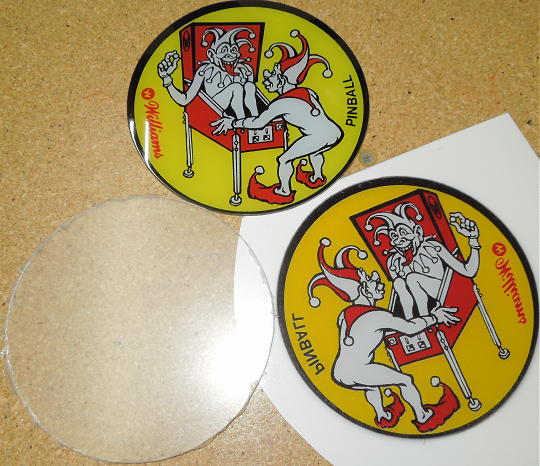
As of 2025 the red and yellow decal at the back of the mini-playfield had not been reproduced. So I needed to salvage the old one. I used up-side-down canned air and the decal popped right off. Residual adhesive was cleaned away with Goo Gone. I scanned the decal for anyone wishing to mess with it. Scan1 Scan2

Canned air.
Although I had a new main decal, I tried removing the old one. Per a suggestion I found on the Internet, I submerged the whole mini-playfield in hot water to soften the adhesive. As shown below, the white didn't survive. This was officially the point of no return.

Failed decal removal.
The flash lamp mounting standoffs were in the way of the red and yellow decal. There was no good way to maneuver the decal with exposed adhesive. I used what I call the "tab method". I applied 3M 467MP transfer tape to the decal with an extended tab of backing paper at one end. The transfer tape was trimmed to size and the adhesive was rubbed off the exposed tap. Then, without any exposed adhesive, I could carefully position the decal with painter's tape. Then I pulled the tab back on itself, exposing the adhesive while removing the painter's tape as I went.

Pulling out the backing paper from right to left.
I similarly applied the new main decal. This wasn't really a "decal", but a thicker, stiff piece of plastic with no pre-applied adhesive. Adhesive was used toward the top, but the decal was mostly held in place by the various hardware pieces. Again, I used 3M 467MP transfer tape with a pull tab on one side.
Transfer tape applied and trimmed.

Pulling out the backing paper from right to left.
The transfer tape adhesive was not perfectly transparent, but could be much improved by carefully burnishing the decals with the back of a finger nail.
I didn't want to go back to concealing the red mini-post mounting screws. I cut a hole in the decal at each mini-post location and switched from the original flat-head screws to truss-head screws. These are the same truss-head screws typically used for mini-posts and playfield plastics.

Truss-head versus flat-head screws.

Red mini-posts installed.
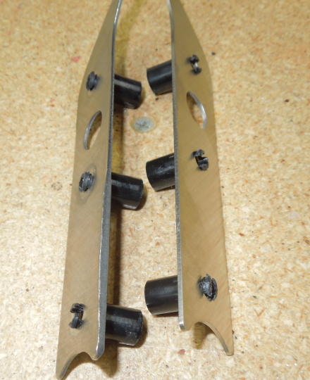
The mini-playfield had a ring on each side. But the lateral ring tension had warped the old mini-playfield. Plus the rings were clunky-looking. I replaced the rings with individual bumpers and guardrails made from 1⁄8" polycarbonate. The rails are about 1 7⁄8" long and 3⁄8" wide with 1⁄4" holes spaced 1 1⁄2" apart. The rails simply rest on the shoulders of the metal posts and should virtually disappear after the game is fully assembled. Mini-playfield ball speeds are low and I doubt a ball would force its way between the bumpers. So I expect the guardrails to act as more of a safety net and not something that would regularly interact with the ball. For more info on how I make plastics, see my Taxi and Millionaire repair pages.

Polycarbonate guardrails.

Clunky intended ring arrangement.

Replacement left bumpers and guardrail.

Replacement right bumpers and guardrail.
The flash lamp sockets and upper lamp board were attached to the mini-playfield with sheet metal screws. I didn't want to risk driving sheet metal screws into my new mini-playfield, so I switched to 6-32 machine screws and pre-tapped the mounting standoffs. For a few extra threads in the flash lamp standoffs, I followed up with a bottom tap. I also tapped 6-32 threads for the two one-way gate mountings.
Machine screws for the mini-playfield mounting standoffs.
I was happy with how the truss-head 4-40 x 5⁄16" screws and nyloc nuts worked for mounting the switch brackets. However, the far-right, lower nut was going to conflict with diode D6 on the lower lamp board. I simply moved the diode to the solder-side of the board. The board traces appeared healthy, but I added a small dab of silicone under the diode as a bit of strain relief.
Switch brackets secured with nyloc nuts.

Relocated diode D6.
All the existing lamps were good. And I reused the existing yellow lamp covers. But I did replace a few of the twist-in lamp sockets that refused to make good contact. I carefully tested all the mini-playfield components before attempting to install the mini-playfield back in the game.
Diode Testing: Each switch diode is installed between the C and NC terminals of its respective microswitch. The NC terminal is employed as a passive connection point between the diode and respective row wire. However, when at rest, the switch shorts the diode. Thus, the switch must be manually closed (breaking the C/NC connection) before the diode can be tested. Maybe I'm dumb, but I was initially scratching my head and wondering why all my switch diodes were shorted.
Bottom done!
I didn't bother installing a new stick-on kwik-klip as I feared damaging the wiring. The wire harness seemed well enough supported by the cutout in the back wall of the main playfield. There was plenty of ball clearance between the main playfield and the underside components and wiring of the mini-playfield.
Implementing the new mini-playfield was a spectacular pain in the ass. I spent weeks on this one sub-project. Much of that time was just mental problem solving and thinking through orders of operation. I wouldn't recommend replacing your existing mini-playfield unless it's completely wrecked.
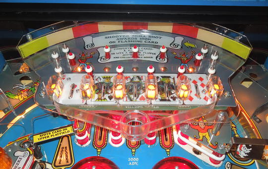
New mini-playfield installed!
I bought a set of three new ramps from Ramp-O-Matic. Unfortunately, reproduction ramp decals were not available (at least as of 2025). I would have had to remove the old switch bracket from the old left ramp (rivets), remove the old left and right ramp decals (risky), remove the new switch bracket from the new left ramp (more rivets), apply the old ramp decals to the new left and right ramps (risky) and reinstall the new switch bracket to the new left side ramp (still more rivets). Instead of doing all that, I just reinstalled the old left and right ramps. Somehow this whole project got bogged down and drug on for a year. I just wanted to get the game back together and play it again. The new ramps aren't going anywhere.
I did replace the right ramp's mangled micro switch with the correct 5647-12073-13.
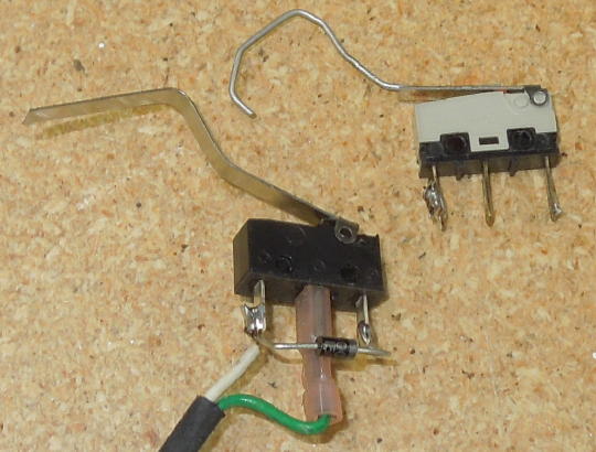
New micro switch.
New shield plastic. Note that this part came from Marco and included the "Double Your Score" decal. The same plastic was with the Planetary Pinball reproduction plastics set, but did not come with a decal.
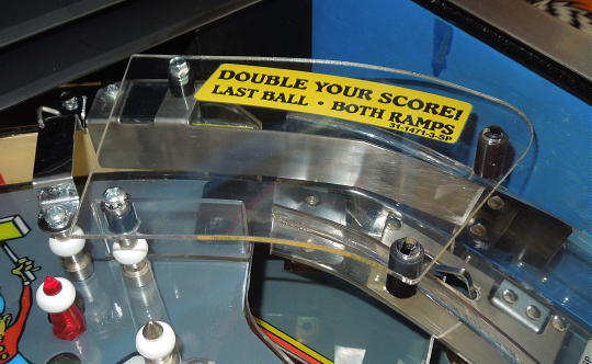
New "Double Your Score" shield replaces the old cracked and yellowed shield.

The old left and right ramps look okay.
Note to future self: The mini-playfield's upper-right support standoff is bent, making it difficult to line up all the components that attach to it. Fix it, replace it or move it somewhere else. Part number 02-4322-13.

Replace or fix this post.
One of the center ramp's flash lamp circuit boards had a blown-out mounting hole. I applied a thin layer of epoxy around the perimeter of the hole a re-tapped it 6-32.
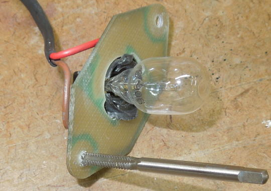
Re-tapping an epoxied hole.
There seemed to be virtually no consensus on the center ramp's support standoff sleeves. But after looking at lots of Internet pictures, two yellow sleeves over one black appeared to be a likely original configuration.
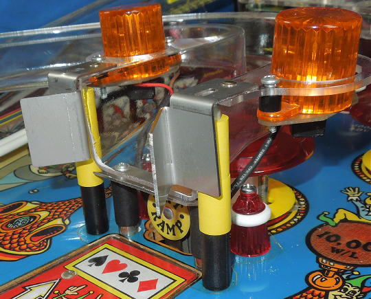
Center ramp sleeve arrangement.
New Ramp-O-Matic center ramp.
The flipper return frames B-12363-L/R were slightly peened, so I bought a new Cliffy's set.
Old flipper return frame (left) versus new.
As previously noted, I saved flipper mech installation for last because of weight, but also because I hate adjusting flippers. I rebuilt the flipper mechs months ago using a rebuild kit I bought years ago. Turns out the Williams kit had Bally flipper bushings. This I did not recognize until I was tightening down the pawl bolts and the plungers began to bind. The mechs had to come back out. At least I got some use out of my new coil connectors.
Williams bushing (left) versus not a Williams bushing.
New shooter spring (10-148-1 standard silver spring), sleeve and tip.
Done!
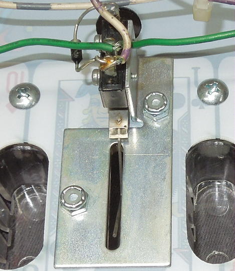
11/30/25: Fixed panel speakers connector. I can't see why this would matter one way or the other. But for what ever reason, the panel speakers connector swapped the trace wire from one side of the connector to the other. According to my other system 11 games, the trace wire should pass through the flat side of the connector, so that's how I put it.
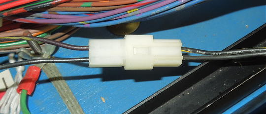
Panel speakers connector.
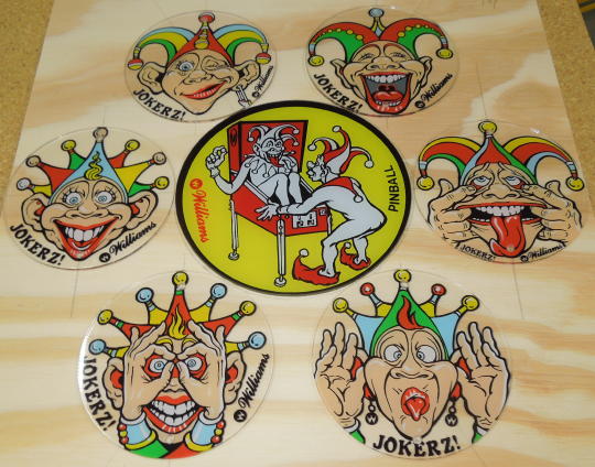
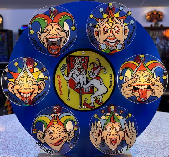
12/28/25: Topper build. I have to say that I despise the artistically inconsistent crap that people insist on sticking on their games these days. In this case I had a collection of artistically consistent pieces in the form of Jokerz! promo plastics. Some of these pieces were included with the reproduction plastics set. Some were eBay finds.

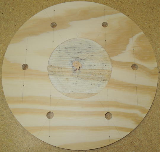
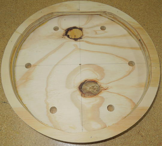
The idea was to build up the topper in layers similar to how a playfield is built up. I started by arranging six of the smaller pieces in an arc around one of the speaker cutouts. After getting the design laid out on a piece of ½" plywood, I used a router and a circle jig to get a clean, consistent arc across the top of the plywood. The remaining cuts were made on a table saw. The arc radius was 10" with the board cut down to about a half-circle. Then I drilled some preliminary mounting and lamp socket holes.
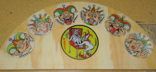
Promo plastics arrangement.
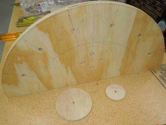
Preliminary mounting and lamp holes and some frisket templates.
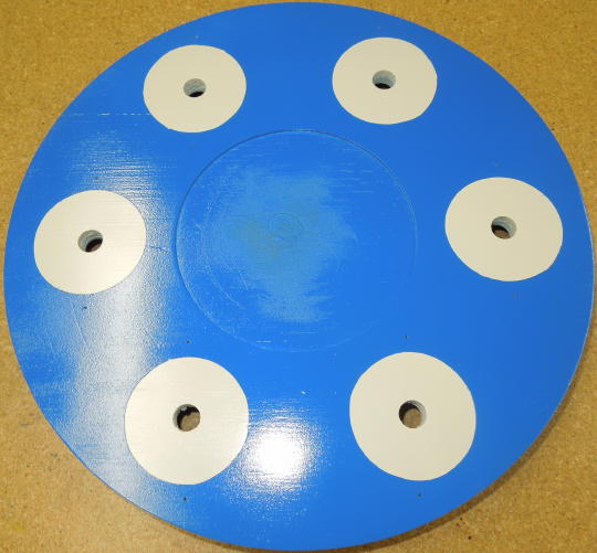
After some filling, priming and sanding, I sprayed the topper an off-white color (because old playfields tend to age to off-white). Then I added a layer of frisket. I wanted the white areas to be slightly smaller than the promo plastics such that the white wouldn't be overly obvious when viewing the topper straight-on. So I used appropriate sized hole saws to make smaller cutting templates. I cut the frisket and weeded away the excess. For sharp lines, I sprayed a light coat of the same off-white. This seals the frisket and prevents the topcoat from bleeding under.
For a topcoat I picked Rust-Oleum Gloss Brilliant Blue. The blue could have been a bit darker, but it was reasonably close to the cabinet blue and looked okay in a dimly lit gameroom.
The images below show the finished topcoat with the frisket removed. It was at that point that I put it up on the game and decided it was too tall and obtrusive. Without destrorying my new paint job, I carefully ripped another inch off the bottom and rebuilt the base.
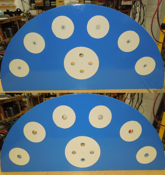
Paint finished (top) and cut down (bottom).
The speaker cutouts were opaque, so I needed to make my own reproduction plastic. For detailed descriptions of how I made plastics, see my Taxi and Millionaire repair pages. In summary, I...
1: scanned the speaker cutout;
2: mirrored the image;
3: printed the image on transparent water slide decal material;
4: applied the decal to a disk of 1⁄8" polycarbonate; and
5: applied a layer of white water slide decal material.
To make a perfectly round disk of polycarbonate without a hole in the middle, I used a router and circle jig to make a template from ½" plywood. With a bandsaw I made a rough-cut disk of 1⁄8" polycarbonate. I temporarily attached the polycarbonate disk to the template with double-sided tape. Then I ran the disk against a flush-cut trim bit on a router table. Finally, I sanded, smoothed and flame polished the edge of the disk.
Unfinished polycarbonate disk, speaker cutout and decal print.
This process always took practice. By my fourth attempt I had come up with something useable. Fortunately, the polycarbonate disk could be recycled by soaking off the offending decals.

My first crappy attempt with my less-crappy fourth attempt.
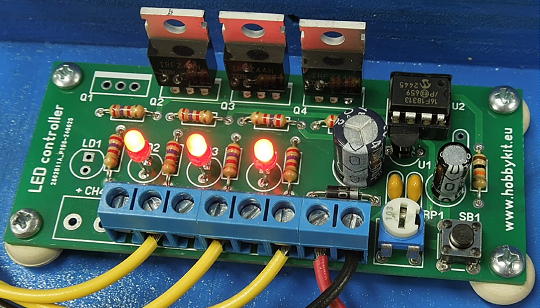
I always wanted to build something with a chase lighting effect. This project seemed like a good candidate since it had six similar plastics lined up in a arc. What I needed was a DC chase circuit with enough current capacity to drive incandescent lamps. I guess I could have built something, but then I found what I was looking for in the form of an HK9983 from www.hobbykit.eu. This was a Bulgarian company, but sold through eBay. Despite eBay and USPS warnings, there was no tariff or punitive COD bullshit. This was late 2025; your mileage may vary.
www.hobbykit.eu HM9983.
The chase effect was only one of sixteen different effects selectable from a button on the circuit board. But the last selected effect was always recalled upon power up. A potentiometer controlled speed.
I wanted to use standard 44/47 type lamps, but the chase circuit required an 8 to 25 volt supply. So I picked a 12 volt supply and wired all my lamps in series pairs. That is, channel one drives the series pair of lamps one and four. Channel two drives the series pair of lamps two and five. Channel three drives the series pair of lamps three and six. Actually, I picked a variable 12 volt supply, so I could dim it all down if desired. Ultimately, I dialed it back to 10 volts. Five volts per bulb looked good and was consistent with some other gameroom lighting projects I've built.
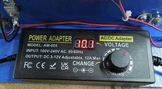
Variable 12 volt supply from Amazon.
Despite using incandescent bulbs, the ON/OFF action of the chase circuit was too harsh. I added a 33 ohm, 2 watt resistor across each of the three output transistors. Thus, all lamps were always partially lit even when their respective channel was inactive.
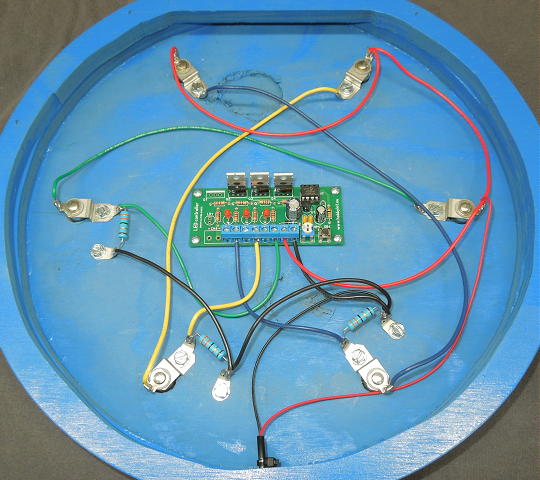
The image below shows the HM9983 schematic. The next image shows how I connected two lamps and a resistor to each channel.
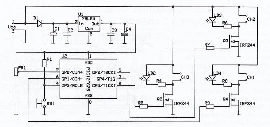
HM9983 schematic.

Lamp and resistor arrangement.
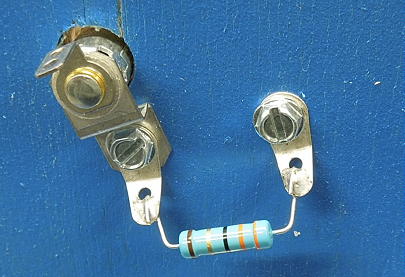
Screw-mount terminals support the resistors.
The center plastic was backlit with four bulbs arranged in two series pairs and connected directly to the power supply.
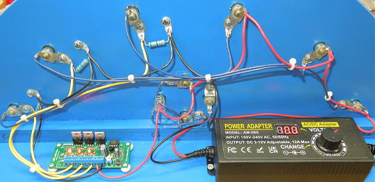
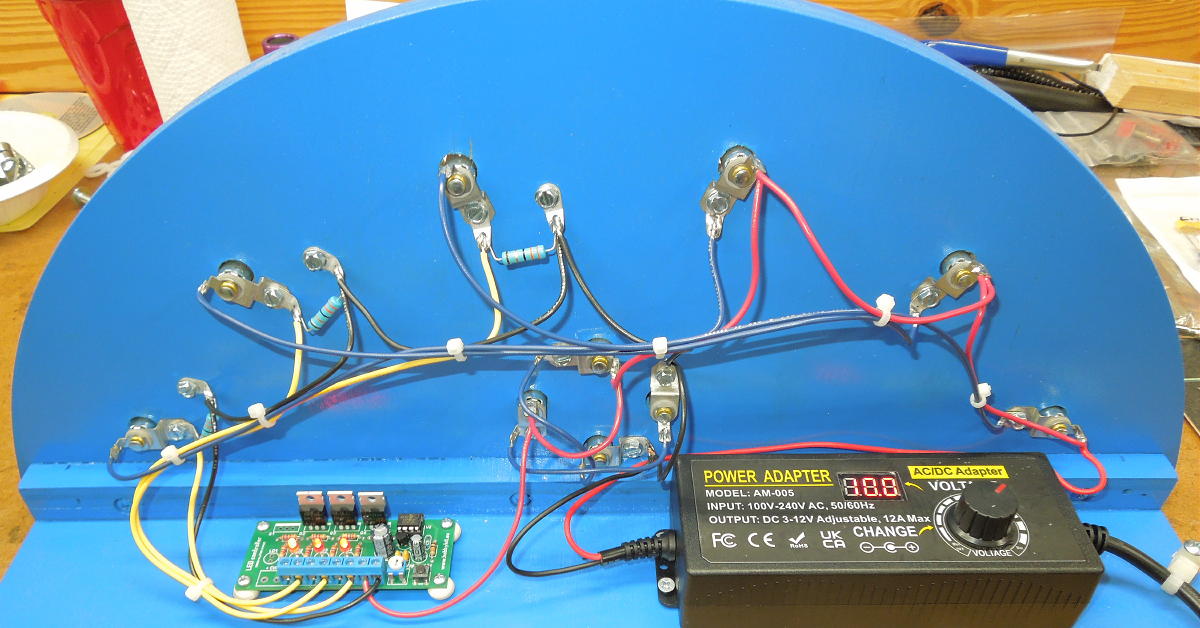
Final wiring arrangement. Click for a larger image.
For final assembly, the plastics were attached via standard Williams red star posts. The topper plugs into a switched wall outlet and comes ON with the rest of the room lighting.
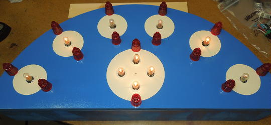
Ready for plastics.
I hate drilling holes in my games, but I didn't think the topper would stay put on its own. So I include a pair of #6 mounting screws.
Screw mounts.
The topper ended up collecting a lot of glare from other elements of my gameroom lighting. The issue could be corrected just by slightly altering the viewing angle. So I ripped a shallow wedge off the side of a 2x4 and stuck the wedge between the game and the base of the topper.
Angle altering wedge.
I still thought the topper was too tall relative to its width. To do it again I'd increase the radius of the arc and reduce the relative chord (i.e. I'd make it noticeably less than a half circle).

Click image to view a brief YouTube video of the finished topper.
04/16/26: Illuminated wall hanging. I lived with the above topper for about four months before scrapping it in favor the wall hanging presented here...
1: I didn't like my homemade plastic. It looked okay by itself, but its sharpness and translucency didn't match the other pieces. Turns out the white decal layer was delaminating, so it probably wouldn't have lasted in the long run.
2: The topper was too bulky and obtrusive.
3: I had a growing dislike for seeing homemade crap attached to classic pinball machines. Building my craft project as a detached, stand-alone wall hanging felt far more respectful.
I reused the topper components, so there wasn't much lost aside from some plywood, paint and hookup wire. I switched from my homemade plastic to an original speaker cutout. Since the speaker cutout was opaque, there was no back lighting. Instead I relied on ambient room light and light reflected from the surrounding plastics.
Promo plastics arrangement.
After drilling lamp socket and mounting holes, I used a router and circle jig to cut a disk from ½" plywood. I routed a shallow center pocket to inlay the speaker cutout.
Cut disk.
I typically add a back perimeter layer of ½" plywood to create a pocket for the lamp sockets and wiring. In this case I added two layers since my chase control module was about an inch tall. I rough-cut the perimeter layers on a bandsaw. After glueing up each layer, I went over the outside edge with a flush-cut trim bit in a router to ensure the back layers matched the concentricity of the front disk. The rear-most layer included a top inside horizontal straight cut with a slight undercut to grab a screw in the wall.
Back perimeter layers.
Finished paint.
Final wiring.
I switched to a more compact 10 volt "wall wart" power supply. The power pack plugged into a switched outlet such that the wall hanging would come ON with the rest of the room lighting.
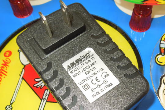
Power pack.
Done!
Done!
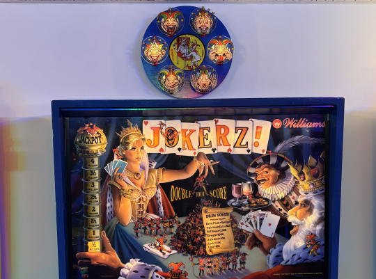
Done!