

The 60 in 1 Guts
I knew virtually nothing about video games. To begin I bought most all my guts from a company called DIY Retro Arcade at diyretroarcade.com. They specialize in converting Arcade1Up games. I had no interest in Arcade1Up. But their Arcade1Up 60 in 1 conversion kit looked to have just about everything I'd need to initiate my learning curve. The kit included the 60 in 1 board plus a pre-terminated JAMMA harness, power supply, amplifier, speakers, controls and more. In addition to the basic kit I also bought a 19" open frame monitor, a trackball and a few extra buttons and other odds and ends. I also ordered one their custom Arcade1Up conversion control panels. I didn't necessarily expect to use the panel in my final project, but it seemed like a quick and easy way to get organized and start experimenting.
The picture below shows most everything I ordered from DIY Retro Arcade plus a few wood scraps to prop up the monitor and control panel. There are good videos on the DIY Retro Arcade YouTube channel showing how everything is connected.
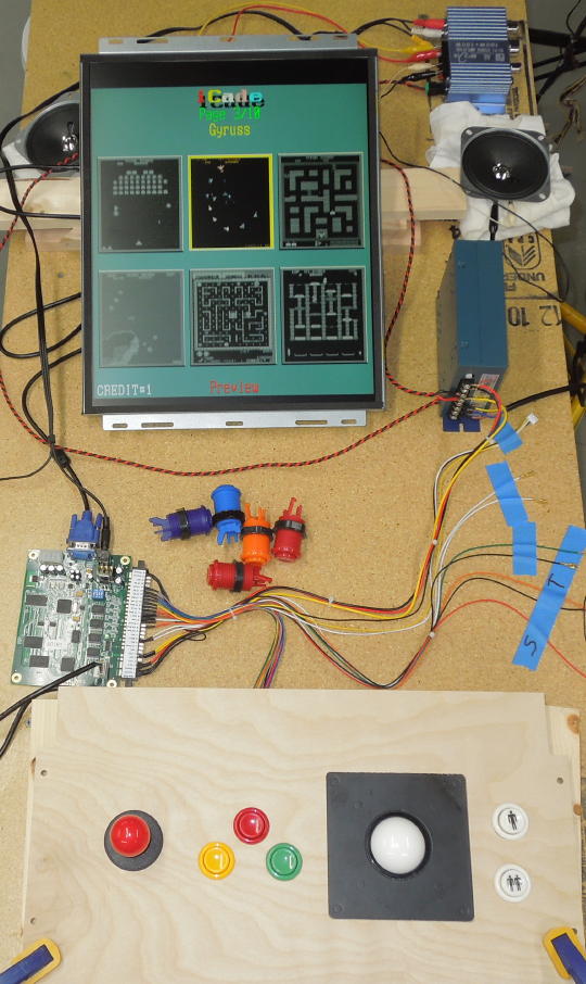
My workbench arcade video game.
60 in 1 Board: My kit included zero documentation. I didn't even get the 60 in 1 manual. But the manual is easy enough to find with a simple Google search. There's not much to say about the 60 in 1 board that hasn't already been well documented on the Internet.

60 in 1 board with VGA, stereo, JAMMA and COM3 connections.
Monitor: I added a 19" open frame monitor which was not part of the basic conversion kit. Again, there was no documentation. There wasn't so much as a brand or model number to be found. The OSD buttons were unlabeled and the OSD itself appeared to be in Chinese. But the image was as expected so I guess there's no need to adjust anything. It's an AC/DC monitor. It seemed flaky under AC power. But it worked well with a 12 volt DC input, which is what I intended. The monitor plugged directly into the 60 in 1 board with a VGA cable. There's an empty black band at the top of the monitor, but that can be hid with a monitor bezel.

19" open frame monitor.

Back side of monitor.

Unlabeled OSD buttons.

WTF does that say?
Buying the open frame monitor was probably dumb. An appropriate PC monitor would have been less than half the cost and arguably more user friendly. But I didn't want to look at my project and see a hacked PC monitor. I was hoping to build something that would "feel" more like a commercial arcade video game. In the end, the monitor did exactly what I wanted it to do.
Joystick: The joystick looks like a JLW-TM-8 type. It has a rotatable restrictor plate to configure the joystick as an 8-way or a 4-way. I have mine configured as a 4-way which is more compatible with the older games I remember. The diagonals are slightly accessible with the restrictor plate rotated to its 4-way position. So it's still possible (if a bit awkward) to play the 8-way games.

Topside of joystick.

Underside of joystick.
Joystick Revisited: While building my cabinet I was looking at various joystick alternatives that included a more easily rotatable restrictor plate. I settled on a Ultimarc ServoStik because it appeared to have a footprint similar to my existing joystick and I wouldn't have to alter my control panel design. I did not purchase the "required" control board.

Underside of the Ultimarc ServoStik.
I wasn't actually interested in having an automated restrictor plate. I initially considered discarding the servo and simply rotating the restrictor plate by hand via the coin door opening. But the servo does serve something of a locking function. Note how the servo horn is at a locking right angle with the restrictor plate when the servo is at its travel limits. So maybe I could operate the servo with a simple toggle switch.
The servo itself is a Vigor "Battery Operated Gearbox" model BO-1. I couldn't resist disassembling the gearbox and counting teeth. It's a four-stage gearbox and is the 1:120 gear ratio version of the BO-1.
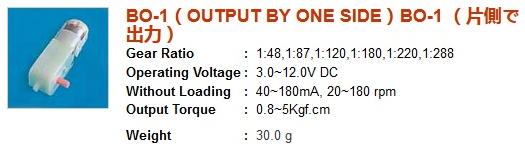
Specs from the Vigor website.

Gearbox innards.
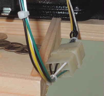
There was no information as to weather the gearbox would be damaged if left in a stall condition. I assume the ServoStik is intended to be operated at 5 volts and the servo produced quite a bit of torque when operated at that voltage. But I found I could operate the ServoStik with as little as 2 volts. After disassembling the restrictor plate and cleaning up some residual flash, the plate moved with little effort. At 2 volts the stall current was 250 mA and I felt that the servo was producing a non-damaging amount of torque. Of course that's just my intuition. Applying a positive voltage to the servo's red wire rotates the restrictor plate to its 4-way position. Applying a positive voltage to the servo's black wire rotates the restrictor plate to its 8-way position.
But my 60 in 1 project has a 5 volt supply, not a 2 volt supply. Nevertheless, I achieved similar results with a 5 volt supply and a 30 ohm current-limiting resistor. The resistor actually works better as it produces a non-regulated voltage across the motor. At a stall the voltage across the motor drops to 1 volt and the stall current is only 122 mA. I watched a bunch of ServoStik videos on YouTube and observed mounting plate flex and rebound. Both of those characteristics appear minimal with my circuit. I recommend picking the largest value resistor that still permits the restrictor plate to rotate.
So my control circuit consists of a 5 volt supply, a 30 ohm resistor and a DPDT, center-off, momentary toggle switch. It's up to me to hold the switch no longer than is necessary to operate the servo. I don't intend this to be a user-operable (except for me) feature. The switch will be safely locked behind the coin door and inaccessible to the casual visitor. The joystick will remain in its 4-way configuration during any sort of open house event.
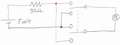
Control circuit.
Turns out that the ServoStik components were entirely compatible with my existing joystick from DIY Retro Arcade. So I transferred just the servo and restrictor plate to my test rig and continued to experiment. I would have only needed to purchase the ServoStik Upgrade Kit, but it was out of stock at the time. Click the image below to view a brief YouTube video of the servo in operation.

ServoStik components on my DIY Retro Arcade joystick. Click image to view a brief YouTube video of its operation.
So why not just buy the ServoStik control board and be done with it? Well mainly because I felt like tinkering with something. But also because it annoyed me that I would be buying a miniature computer solely for the purpose of operating one servo. Shouldn't there be a simpler way? I wanted this project to have more of an old-school, low-tech vibe to it. That said, if you're not a tinkerer you should just buy the control board, program it to hardware mode and use it all as it was intended to be used.
A few more notes: The restrictor plate tensioning springs are a bit small in diameter. The springs tend to thread themselves into the nylon washers as the screws are tightened. As received, one of my springs was halfway under its respective washer. The ServoStik does not include a joystick ball.
Okay, back to my DIY Retro Arcade components...
Buttons: Typical buttons in multiple colors with included micro switches.

Buttons and micro switches.
Trackball: The 2.25" trackball was another addition that was not part of the basic conversion kit. It included a cable and connector which plugged right into the CON3 port on the 60 in 1 board. Again, there was no documentation. The trackball may originate from some place called "Atomic Market", but I could find no further information. I correctly guessed that the trackball should be installed in the control panel with the cable pointed toward the monitor. I correctly guessed that the trackball should be plugged into CON3 (as opposed to CON4). It was plug-n-play and worked straight away. The trackball functions in parallel with the joystick. That is, either control can be used for most any game. But the trackball is more appropriate for the Centipede and Breakout type of formats.

Topside of trackball.

Underside of trackball.
These trackballs are pretty inexpensive. And since I couldn't find documentation or any indication of replacement parts, I bought a spare unit for safe keeping. As shown below, there are no ball bearings. The ball is not as free-rolling as an authentic arcade trackball, but it feels fine to me.

Trackball guts.

Trackball guts.
The trackball case has four mounting holes. One of the four holes was ever so slightly smaller than the other three. Perhaps this was for some sort of mounting index. But the small hole was too small for the studs on the steel mounting plate. It was a simple matter to drill out the smaller hole. The steel mounting plate is shown below. The inner studs fit into the trackball case. The outer studs mount to the control panel. The included nuts didn't fit on the outer studs because of too much paint. An M4 die was needed to clean out the threads.

Trackball mounting plate.
Control Panel: The custom control panel was intended for an Arcade1Up conversion. I didn't think I'd use it in the long run, but I ordered it because I wanted to start playing around without taking the time to cut my own. The control panel included the steel plate for mounting the trackball. I'm guessing the control panel layout was dictated by its compact size. It may not be ideal. The triangular configuration of the buttons doesn't seem very ergonomic. A row or an arced row of buttons may be more desirable. The buttons are connected from left to right as S2 S1 S3. This may have been done to keep the most used fire button up top. But S1 S2 S3 may make more sense. For example, Gun.Smoke is the only game to actively use all three buttons and is clearly intended for an S1 S2 S3 button layout. I found a website at www.slagcoin.com that probably has more information about control panel ergonomics then you'd ever want to know.

Control panel.
The end of my workbench was a good place to experiment with various heights and angles for the control panel. I also changed the button order to S1 S2 S3.

Control panel placement testing.
JAMMA Harness: JAMMA wire harnesses come in different flavors of complexity. This one was just right with all the wires I needed and none that I didn't. For example, there were no wires for player two controls. I'll end up using all the wires except for the speaker output. The harness female spade connectors have small tabs that lock with holes in the micro switch terminals. If, like me, you're looking to experiment, be sure to orient the spade connectors such that the terminal holes are accessible. If you want to move things around, you need to poke something pointy in the hole to disengage the connector. I went to Amazon and found Baomain 4.8 mm female spade crimp connectors that look to be exact replacements for what was on my JAMMA harness. I added my own connector to interface with the coin door.

JAMMA connector.

Crimp connectors.
Coin door connector.
Power Supply: A typical Chinese 12V/5V power supply which is included with many 60 in 1 kits. My kit also included a separate power switch/EMI filter and a connecting cable.

Power supply.
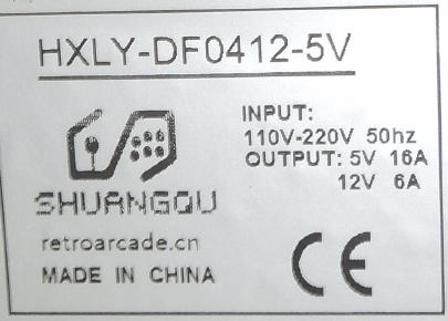
Power supply label.
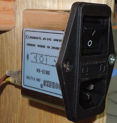
Power switch/EMI filter.
Amplifier and Speakers: The 60 in 1 board includes a built-in mono amplifier with a speaker output at pins 10 on the JAMMA connector. Most games are mono and the built-in amplifier would work just fine to power a single speaker (although I'd recommend an easily accessible passive volume control). Nevertheless, my 60 in 1 kit included two small speakers and a no-name external stereo amplifier. In addition to the built-in mono amplifier, the 60 in 1 board has a stereo output in the form of a 3.5 mm stereo line output. The menu volume control is for the built-in mono amplifier and has no effect on the line output. The potentiometer on the 60 in 1 board is for the built-in mono amplifier and has no effect on the line output.
The two-channel line output is well demonstrated by the game Gyruss. I don't know that I'd call it "stereo" per se, but there's clearly two channel's worth of sound effects which makes for a neat audio experience. Unfortunately, Gyruss may be the only two-channel game and is one of the games that suffer from the infamous 60 in 1 sound distortion. I'll use the external amplifier because I have it, but would otherwise not recommend the bother.
The 180 watt claim on the amplifier case is comical. Nevertheless, I experimentally connected the amplifier to a decent pair of bookshelf speakers and it sounded okay. I found this same amplifier on Amazon listed under "Autut" with an "undistorted power" rating of 25 watts at 4 ohms. My kit included an RCA Y-cable to patch between the 60 in 1 board and the amplifier.

Amplifier front.

Amplifier label.

Amplifier connections.

The 4" kit speakers.
The two 4" speakers that came with my kit seemed kind of insignificant and I didn't think I'd use them in my final project. Without really knowing anything about speakers, I went to Amazon and bought a "better looking" pair of 4" speakers. I like that the cone surround doesn't protrude beyond the frame so I can still flush mount them to the inside of my cabinet.
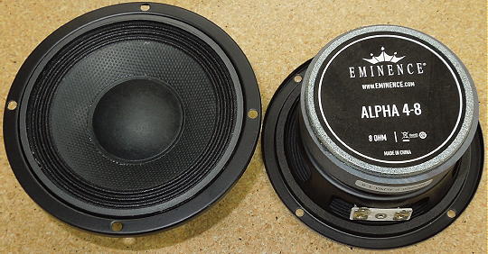
Eminence Alpha 4-8 speakers.
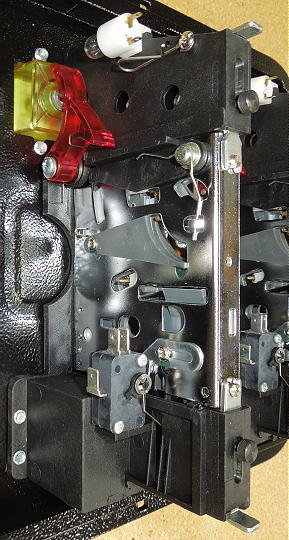
Coin Door: I looked at eBay for an old coin door, but only found a lot of expensive scrap metal. So I went to Twisted Quarter and bought a brand new coin door. I imagine this is yet another Chinese knockoff, but was described as a "Wells-Gardner Style Pinball Door". It was cosmetically similar to the coin doors on all my Williams pinball machines which was neat. But you get what you pay for. The door will be okay for my application, but was pretty cheesy with many parts made from soft plastic and held together with easily strippable sheet metal screws.

Twisted Quarter coin door.
Most everything was included including a pair of quarter mechs, but not the carriage bolts which were sold separately. Weird that a "Pinball Door" would come with 12 volt lamps, but that's exactly what I needed for this project. I could do without the yellow Twisted Quarter reject buttons and may look for a more generic orange replacement.
Quarter mech and micro switch.
A few tweaks were needed. One of the micro switches didn't work because its internal spring had not been properly installed. It was easy to take apart, but required a magnifying glass to spot the problem. Each entry bezel had a restrictor plate with a protruding peg to block anything with a diameter larger than a quarter. But the slot was annoying narrow so I carved it out. Just for personal preference, I added amber reject buttons with generic inserts (from somewhere on eBay). And I replaced the lamps with a pair 194-type amber automotive LEDs I found in a junk drawer. I also added my own lock which is keyed to everything else in my gameroom.

Modified (left) restrictor plate.

Amber reject button with generic insert.
Next I made a wire harness. I already had all the wire colors I needed to match the JAMMA harness and a I re-pinned an old pinball connector to interface between the two. Unlike all the other controls in this project, the coin door micro switches required 6.3 mm spade connecters and the NO/NC terminals were opposite relative to the common. Again, I went to Amazon and bought Baomain 6.3 mm female spade crimp connectors.
My JAMMA harness had a coin door wire bundle including two coins, two grounds and 12 volt power. Alternately, I could have used one coin wire and connected the micro switches in parallel. The 60 in 1 has no bookkeeping, but each coin wire can be set to give different credits for different denominations. But both my mechs take quarters so it didn't matter.

Wire harness.

Lit reject buttons.
On to the next part: Cabinet Construction.
