Solarbotics Solar Marble Machine

Solarbotics is primarily a supplier of hobbyist robotic components. But I found this marble machine under their Kits - Desk Toys category. The laser-cut parts are made from a thin Masonite-like type of hard board.
--EXTERNAL LINK-- Click image to go to YouTube video of finished model.

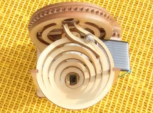
Finished model.

Finished model.

Finished model.

Finished model.

Next to a beer can for scale. The model is pretty petite

Box and parts.

Electronic parts.

After assembling the electronic parts, this picture shows the motor, the "Solar Engine" circuit board and the solar cell.

Close up of the assembled "Solar Engine" circuit board.

Rough schematic of the circuit arrangement.
The "Solar Engine" circuit board shown above appears to be a newer development. Older information indicates that the circuit components and motor leads were all soldered directly to the circuit board on the underside of the solar cell without any other intermediate circuit board.

Here's the circuit board on the underside of my solar cell as finished. Most of the traces now go unused.

Here's a random picture from the Internet showing the old method of mounting all the components directly to the solar cell circuit board without the intermediate "Solar Engine" circuit board shown above.
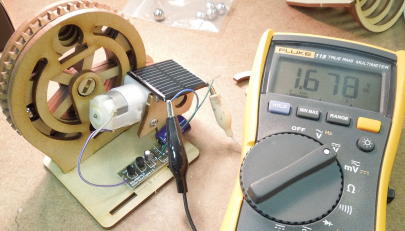
The 1381L "Trigger" is a voltage detection IC typically used in power-ON-reset applications. The "L" suffix indicates a detection voltage of about 3 volts. This voltage is offset by the diode so the circuit operates between about 3.7 volts and 0.6 volts as shown in the video below. The solar cell slowly charges the big 4700uf capacitor. At about 3.7 volts the detector triggers the transistor which discharges the capacitor through the motor. In bright direct sunlight the motor pulses once about every three seconds. In dimmer indoor light the motor may only pulse once every few minutes or not at all if the solar cell is unable to overcome inherent circuit losses. The amount of light also influences the degree of rotation per pulse. In bright direct sunlight the model may eject a ball in as few as five pulses. In dimmer light there may be twelve or more pulses between balls entering the spiral. The model would live happily on a windowsill.

Here's the final placement of all the components before adding the spiral assembly.
--EXTERNAL LINK-- Click image to go to a YouTube video showing the model's voltage response.
For the most part my marble machine worked well right from the start. But I noticed one hole in the gear wheel assembly where the balls tended to balance themselves on the edge of the gear wheel (part d) and not drop off into the spiral. Fortunately I had not glued any of these parts as they tend to hold themselves together just by friction. I disassembled the parts and used a hobby knife to add a slight bevel to the holes as shown below. I also added an even slighter bevel to part c. Friction didn't work as well the second time around so added some glue to reassemble the parts. Now the model performs consistently.

The right hole has been modified with a slight bevel.

I also added a slight bevel to part c.
I wedged a piece of flat toothpick over the inside tip of the spiral as shown below. The spiral worked just fine, but I thought the toothpick added a more flowing look to the end of the spiral.

Toothpick wedged over the inside tip of the spiral.

Toothpick wedged over the inside tip of the spiral.

Never did figure out the purpose of this part. Glue stick?

Some of the parts look a lot like the scrap pieces. I didn't trash anything until the model was fully assembled and tested.


